Self-pumping, hydropneumatic suspension strut unit

a technology of hydropneumatic and suspension struts, which is applied in the direction of mechanical equipment, vibration dampers, and suspensions that are resilient, can solve the problems of not being able to use unmodified leaf springs, reducing the strength of leaf springs, and suspension strut units with self-pumping and hydropneumatic internal level control, etc., and achieves the effect of easy retrofitting

Inactive Publication Date: 2005-03-29
ZF SACHS AG
View PDF5 Cites 17 Cited by
  • Summary
  • Abstract
  • Description
  • Claims
  • Application Information

AI Technical Summary

Benefits of technology

Advantageously, the leaf spring mechanism already present in the vehicle can be retained, so that the chassis can be easily retrofitted for implementing level control.
Since the leaf spring allows the vehicle to travel elastically outward to an extreme distance in the unloaded state, a means for providing an elastic force which opposes outward excursion of the piston rod is included to return the vehicle body back to an appropriate level.

Problems solved by technology

Disadvantageously, suspension strut units are not designed for commercial vehicles (e.g. small delivery trucks, etc.) equipped with leaf-spring suspensions and used to transport heavy useful loads.
In such commercial vehicles, the leaf spring not only guides the axle but also absorbs torque, so that reducing the strength of the leaf spring is not an option.
A suspension strut unit with self-pumping, hydropneumatic internal level control, however, cannot be used with an unmodified leaf spring because the body of the vehicle would otherwise be raised far too high in the unloaded state.

Method used


Image

  • Self-pumping, hydropneumatic suspension strut unit
  • Self-pumping, hydropneumatic suspension strut unit
  • Self-pumping, hydropneumatic suspension strut unit

Examples


Embodiment Construction

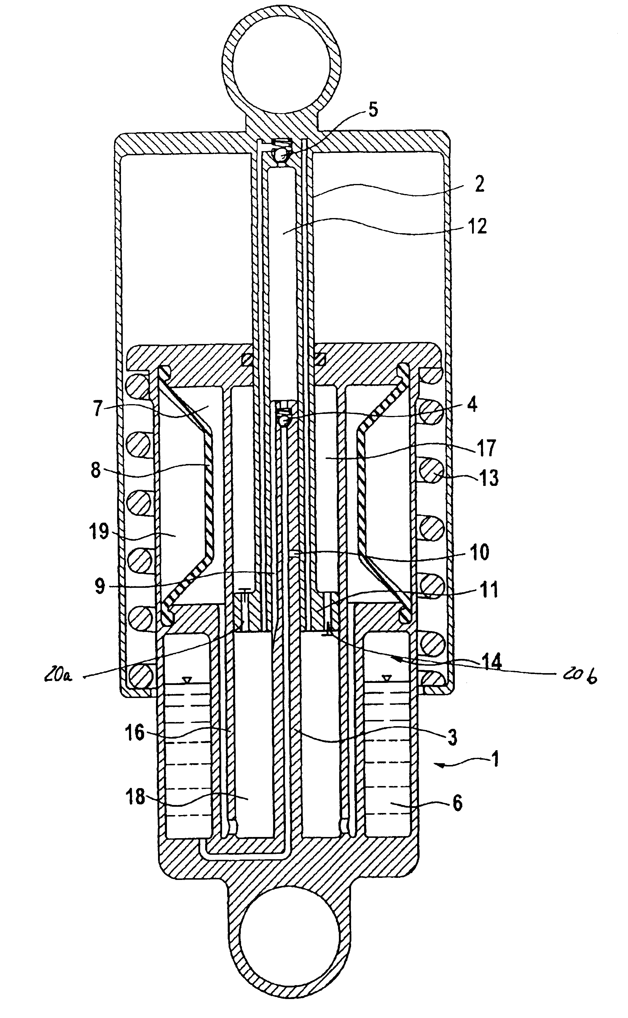
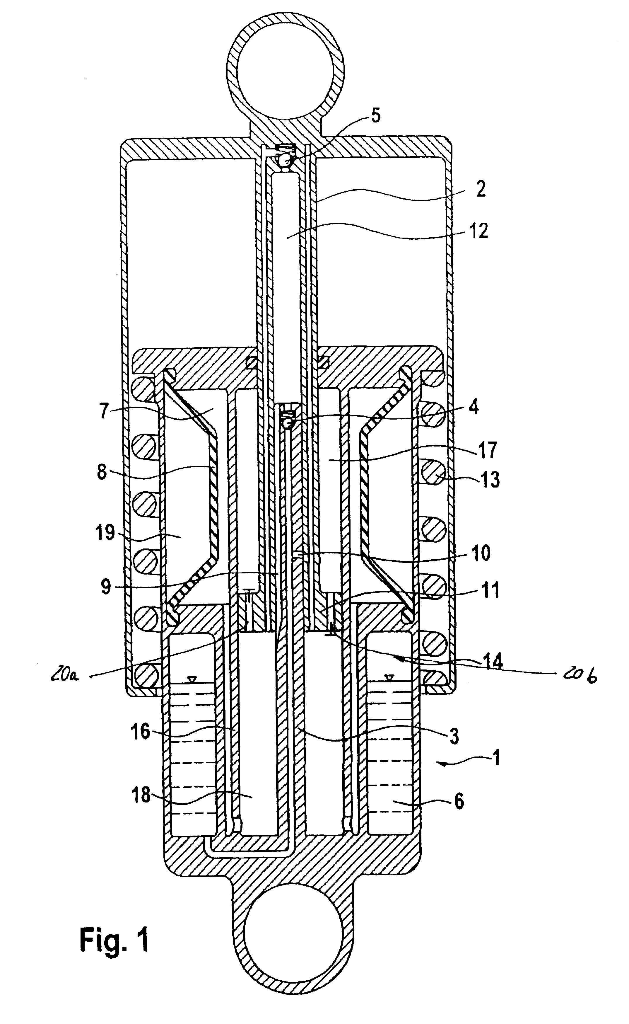
The self-pumping, hydropneumatic suspension strut unit 1 shown in FIG. 1 with internal level control comprises of the working cylinder 16 of the suspension strut unit 1 in which a piston 11, mounted at the end of the piston rod 2, is freely slidable. Working cylinder 16 is closed at one end by a base and at the other end by a cover through which the piston rod 2 emerges to the outside through a seal. The base and the piston rod 2 are each provided with fastening elements (not shown), by which they are attached to the body of the vehicle and to the vehicle axle, respectively.

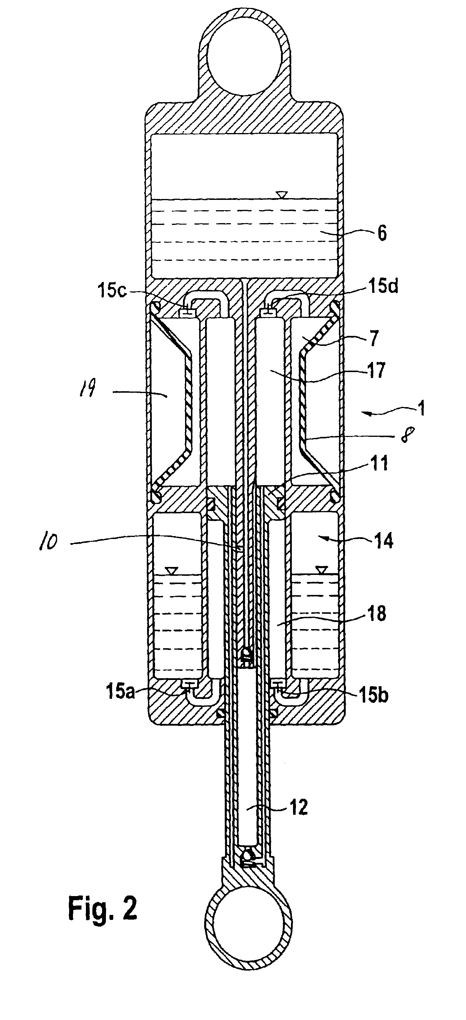
The working cylinder 16 is connected to a low-pressure chamber 6 and to a high-pressure chamber 7, which are filled partially with oil and partially with gas. Working cylinder 16 is divided by piston 11 into two working spaces 17, 18. Piston 11 itself includes damping valves for the tension and compression stages 20a, 20b.

The level control function of the self-pumping, hydropneumatic suspension strut unit 1 is r...


PUM


Abstract

A self-pumping, hydropneumatic suspension strut unit with an internal level control for a vehicle includes a low pressure chamber and a high pressure chamber for storing a damping medium under pressure. The high pressure chamber includes a gas cushion for displacing the damping medium therefrom when the damping medium is under less than a predetermined pressure. A working cylinder has a piston that defines a first volume of the working cylinder in fluid communication with the high pressure chamber. A piston rod is axially displaceable in inward and outward relative to the working cylinder. A pumping rod is axially mounted at one end in the working cylinder and a regulating bore is disposed at a first location of the pumping rod. The bore is closed when the first location is received in the piston rod and places the low pressure chamber in two-way fluid communication with the first volume when the regulating bore is open. A cavity is located axially in the piston rod for receiving the pumping rod and provides a one-way fluid communication from the low pressure chamber to the first volume. A bypass is disposed at a second location on the pumping rod and is closed when the second location is received in the piston rod for placing the cavity in fluid communication with the first volume when the bypass is open. The piston rod is elastically urged in the inward direction so that when the pressures in the low and high pressure chambers are equal, the piston rod and pump rod cooperatively increase the high pressure chamber pressure to the predetermined pressure whereupon the damping medium displaces the piston outward until the regulating bore hole is open to equalize the pressure of the low and high pressure chambers.

Description

BACKGROUND OF THE INVENTION1. Priority ClaimPriority is claimed for this invention and application, a corresponding application having been filed in Germany on May 16, 2002, No. 102 21 833.1-12.2. Field of the InventionThe invention relates to a self-pumping, hydropneumatic suspension strut unit with an internal level control.3. Description of the Related ArtSelf-pumping hydropneumatic suspension strut units with internal level control intended for use in passenger vehicles are known in the art, for example in DE 198 36 487 A1. A passenger vehicle of this type has a suspension, which typically includes a suspension spring and a shock absorber. When it is desired to use a self-pumping hydropneumatic suspension strut unit, the normal suspension spring is replaced by a weaker suspension spring, since most of the useful load in a passenger vehicle will be carried and controlled by the self-pumping hydropneumatic suspension strut unit.A suspension strut unit of this type has a pump rod w...

Claims


Application Information

Patent Timeline
Patent Type & Authority Patents(United States)
IPC IPC(8): B60G17/044B60G17/04F16F9/00F16F9/08F16F9/06F16F9/32F16F9/50
CPCF16F9/08B60G17/044F16F9/50
Inventor BECK, HUBERT
Owner ZF SACHS AG
Why Eureka
Try Eureka