Eureka AIR delivers breakthrough ideas for toughest innovation challenges, trusted by R&D personnel around the world.

Spring nut adapter

a technology of spring nuts and adapters, which is applied in the direction of fastening means, screws, threaded fasteners, etc., can solve the problems of increasing the difficulty of installation and maintenance of construction using u-shaped channels, and achieves the effects of simple installation and maintenance, low manufacturing cost, and easy installation

Inactive Publication Date: 2005-03-29
SCOTT RALPH F JR
View PDF17 Cites 38 Cited by
  • Summary
  • Abstract
  • Description
  • Claims
  • Application Information

AI Technical Summary

Benefits of technology

It is, therefore, an object of the present invention to provide a spring nut adapter that overcomes the deficiencies of the prior art. It is another object of the present invention to provide a spring nut adapter that is attachable to the free end of a compression spring on a spring nut, which would allow the spring nut to freely slide along a channel. It is another object of the present invention to provide a spring nut adapter that is inexpensive to manufacture and easy to install. It is still a further object of the present invention to provide a spring nut adapter that is simple in its installation and maintenance in the field.
The present invention is a spring nut adapter for use in connection with a substantially U-shaped channel, the channel having a base plate and two side plates and channel grooves on upper portions of the side plates. The spring nut adapter includes a face plate having an attachment orifice extending therethrough. The spring nut adapter further includes a compression spring having a first and second end, with the first end of the compression spring secured to an underside of the face plate and extending away from the face plate. An adapter element is secured to the second end of the compression spring. The adapter element is sized and shaped such that, when the combined face plate / compression spring / adapter element is slid laterally along the grooves of the channel, the second end of the spring slides with the adapter element, thereby preventing the second end of the spring to catch on the base plate of the channel.

Problems solved by technology

This, in turn, increases the difficulty involved with installation and maintenance of construction utilizing the U-shaped channels.

Method used


Image

  • Spring nut adapter
  • Spring nut adapter
  • Spring nut adapter

Examples


first embodiment

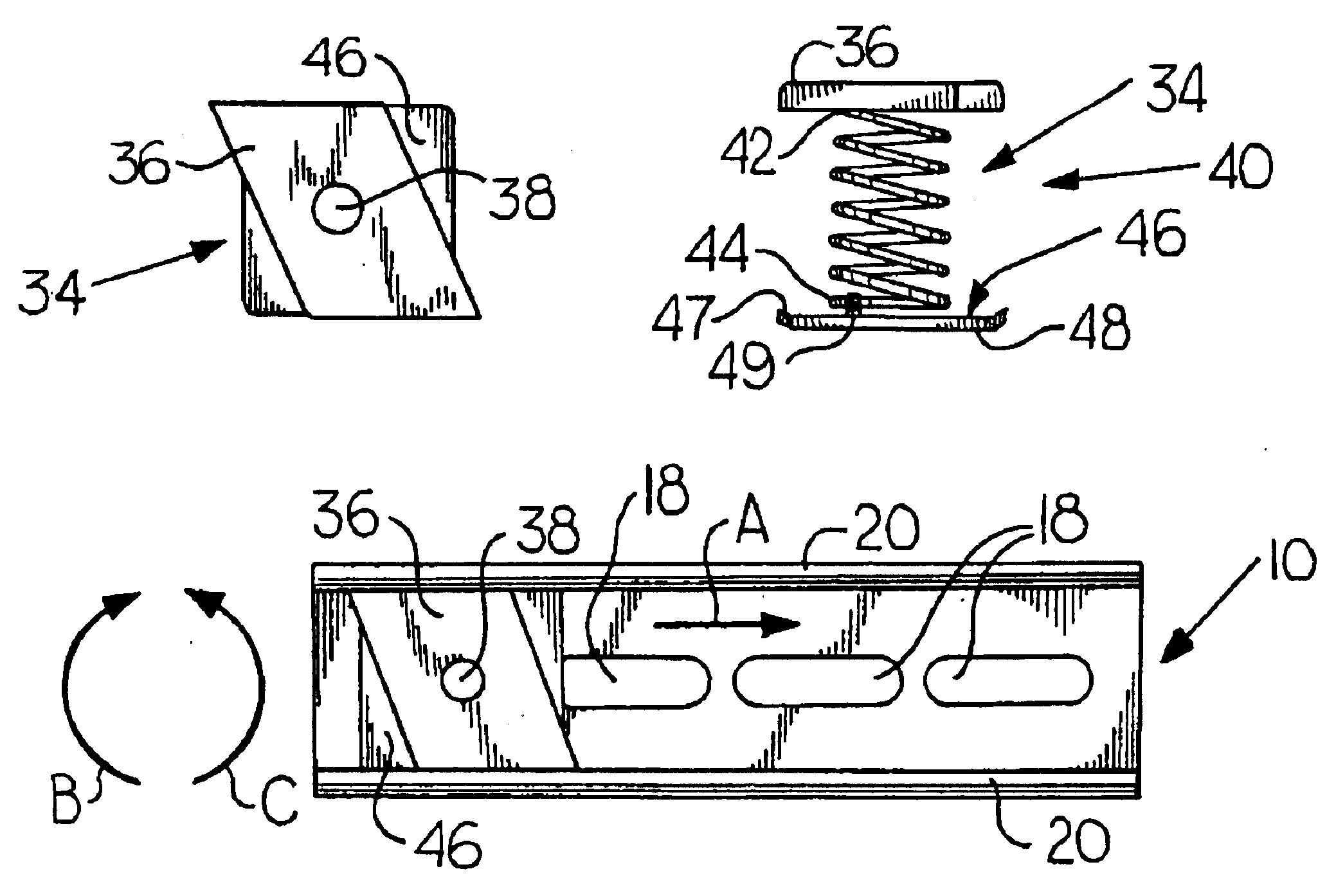
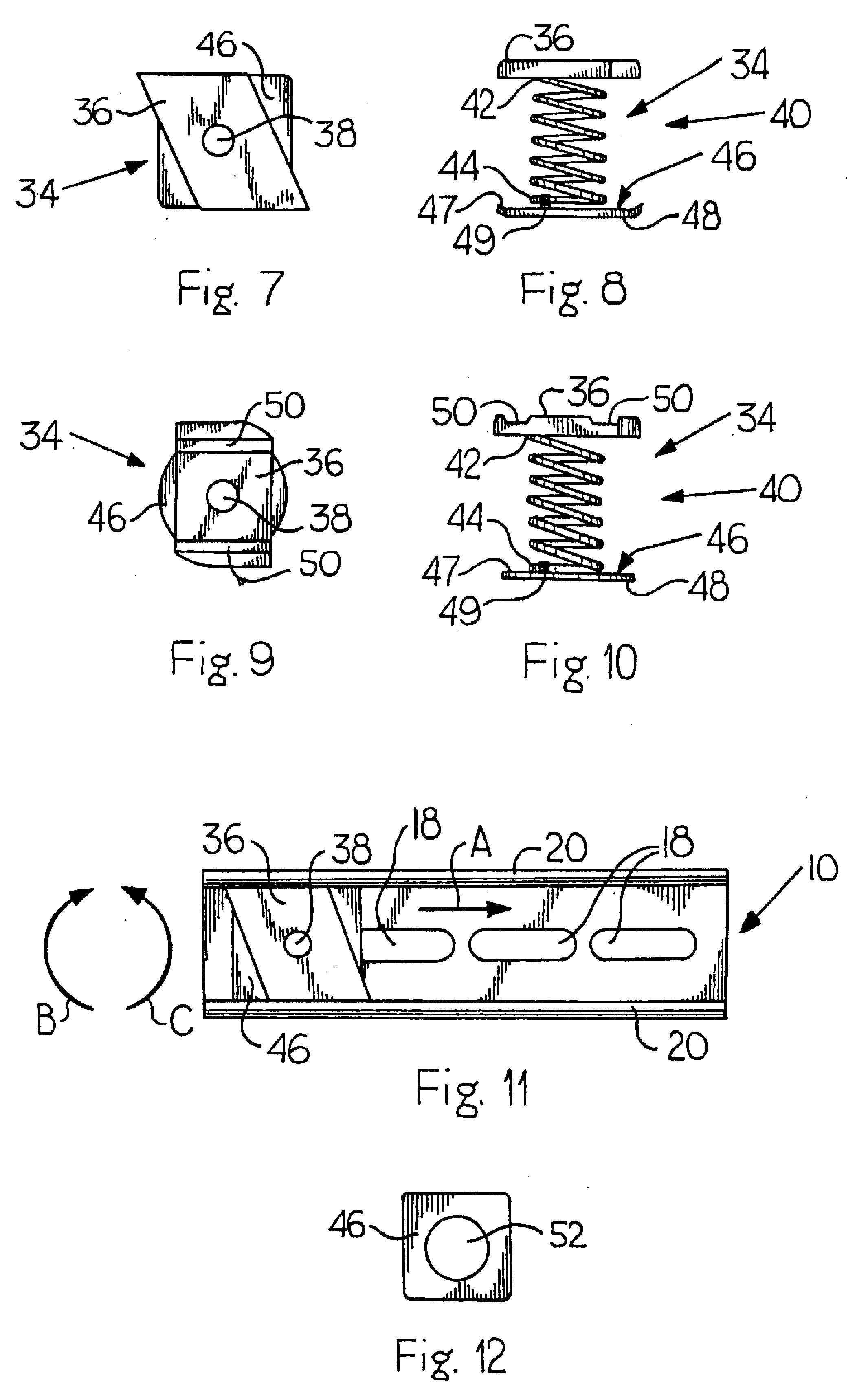
Turning to the present invention, a spring nut adapter 34 according to the present invention is illustrated in FIGS. 7 and 8. The spring nut adapter 34, as with the prior art, includes a face plate 36 having an attachment orifice 38 extending through the face plate 36. Further, a compression spring 40 is attached to an underside of the face plate 36, and the compression spring 40 has a compression spring first end 42 and a compression spring second end 44. The compression spring first end 42 is secured to the underside of the face plate 36. The compression spring second end 44 is secured to an adapter element 46.

In the present embodiment, the adapter element 46 is a substantially square-shaped element with a dimension less than the width of the base plate 12 of the channel 10. However, the adapter element 46 can be square-shaped, rectangular, circular, etc. In addition, in order to allow easier lateral movement, the corners of the adapter element 46 may be beveled or rounded.

Still f...

second embodiment

a spring nut adapter 34 according to the present invention is illustrated in FIGS. 9 and 10. In this embodiment, the face plate 36 includes face plate grooves 50 which are adapted to allow the end of the channel groove wall 20 to be at least partially inserted into the face plate groove 50. When the spring nut adapter 34 is engaged with the channel 10, the face plate grooves 50 allow the spring nut adapter 34 to be more easily slid laterally along the channel 10. In this embodiment, the adapter element 46 is substantially circular in shape, which also allows for easier lateral movement. In addition, the face plate 36 has at least two beveled or rounded corners, which allow for partial rotation of the face plate 36. Further, the face plate 36 typically is in the shape of a parallelogram.

FIG. 11 shows the spring nut adapter 34 engaged with the channel 10. As discussed above, the compression spring 40 is slightly compressed, and the spring nut adapter 34 is fed into one end of the chan...


PUM


Abstract

A spring nut adapter for use in connection with a U-shaped channel. The channel has a base plate, two side plates and channel grooves on upper portions of the side plates. The channel grooves are bounded by channel groove walls. The spring nut adapter includes a face plate with an attachment orifice extending therethrough, and a compression spring with a first end and a second end. The first end of the compression spring is secured to an underside of the face plate; an adapter element is secured to the second end of the compression spring.

Description

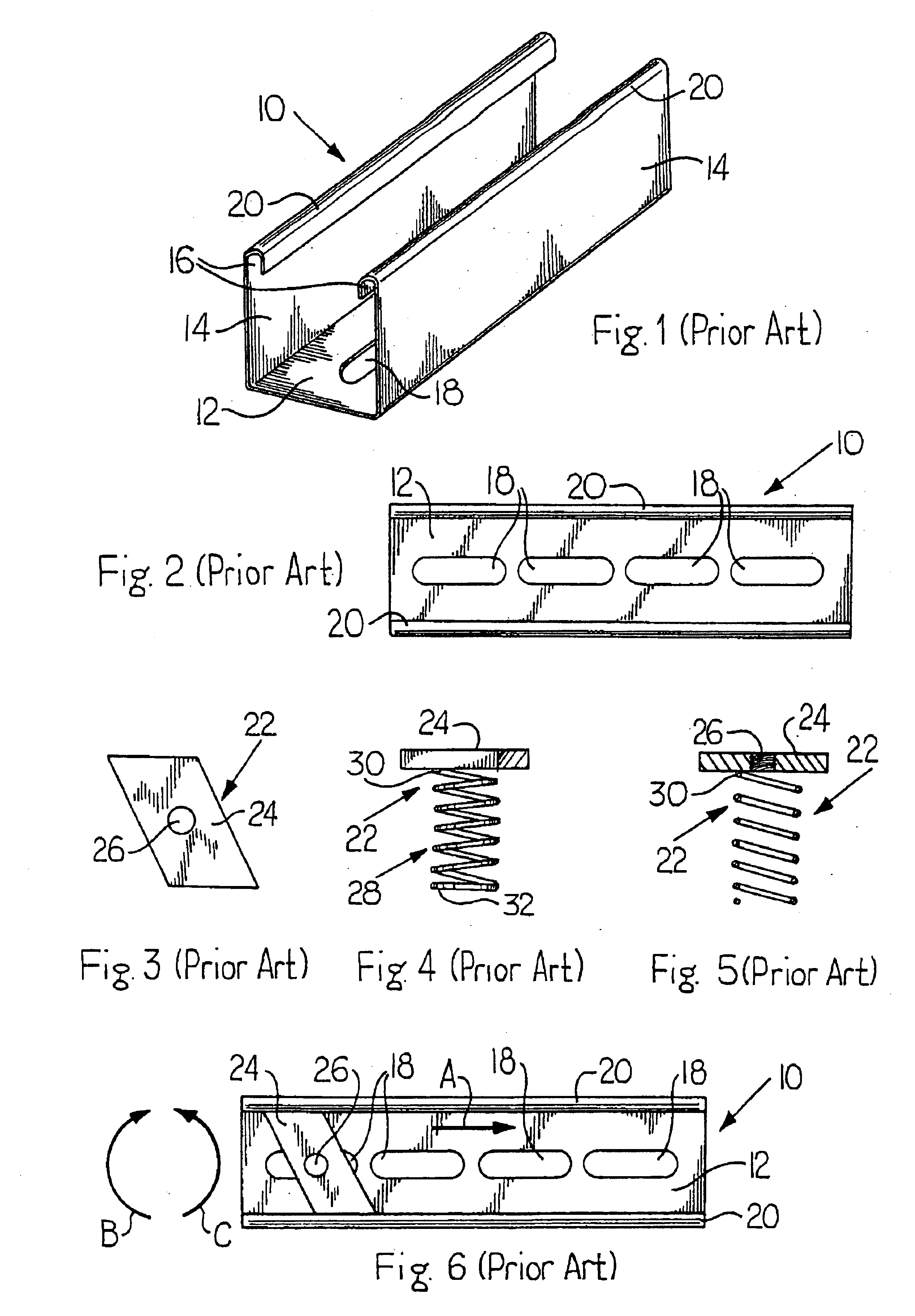
BACKGROUND OF THE INVENTION1. Field of the InventionThe present invention relates generally to spring nuts, and, in particular, to spring nuts used in connection with channels and frames.2. Description of the Prior ArtIn virtually all construction trades and maintenance installations, U-shaped channels and frames are used for constructing support structures or providing conduits for electrical / cable wiring. For example, see U.S. Pat. No. 5,118,233 to Mitchell. In order to fasten face plates or other objects to the U-shaped channels, a spring nut is used by sliding the spring nut into the channel.Specifically, the spring nut uses a face plate having a screw orifice to provide a means for attaching other objects to the channel. In order to urge the face plate of the spring nut towards ends of side plates of the frame, a compression spring is used. The user may simply slide the face plate / compression spring structure along the channel. However, if a base portion or plate of the channel...

Claims


Application Information

Patent Timeline
IPC IPC(8): F16B37/04
CPCF16B37/046
Inventor WESTLAKE, PATRICK C.
Owner SCOTT RALPH F JR
Why Eureka
Eureka Blog
Learn More