Fastener including a screw and a supporting element

a technology of supporting elements and fasteners, which is applied in the direction of screws, fastening means, pins, etc., can solve the problems of not being able to be properly mounted in the assembly station, the risk of the supporting element being clamped in the thread runout region, and the inability to produce in an economic way

Inactive Publication Date: 2005-03-29
KAMAX HLDG
View PDF15 Cites 191 Cited by
  • Summary
  • Abstract
  • Description
  • Claims
  • Application Information

AI Technical Summary

Benefits of technology

There is a number of different possibilities of designing the enveloping cone being located at the supporting element and being arranged to surround the end of the thread of the screw. In a first exemplary embodiment, the surface elements are formed by separate, local impressions being located at the supporting element, the impressions being uniformly spaced apart the circumference of the inner surface of the supporting element. The supporting element at least includes two local impressions. Preferably, it includes at least three or four impressions. However, it may include even more impressions. These local impressions are usually produced after having pushed the supporting element onto the screw. In this way, there is the advantage of the surface of the screw not being damaged.
Another possibility is to design the surface element as a continuous inclined surface being located at the supporting element. Such an inclined surface practically forms a truncated cone being continuous about the circumference to form the envelope. This inclined surface—as well as the surface elements being formed by the impressions—is a surface being located at the inside of the supporting element to face and to cooperate with the upper end of the thread of the threaded portion of the screw. The upper end means the end facing the head of ...

Problems solved by technology

Even shorter thread runouts are theoretically possible, but they cannot be produced in an economic way since the usable periods of time of the tools serving to roll the thread are comparatively short.
Due to the resulting vibrations, there is the danger of the supporting element getting fixedly connected to and engaging the screw such that the known fastener cannot be properly mounted in the assembly station.
Even when the fasteners are separately fed to their place of application, there is the danger of the supporting element getting clamped in the region of the thread runout during trans...

Method used


Image

  • Fastener including a screw and a supporting element
  • Fastener including a screw and a supporting element
  • Fastener including a screw and a supporting element

Examples


Embodiment Construction

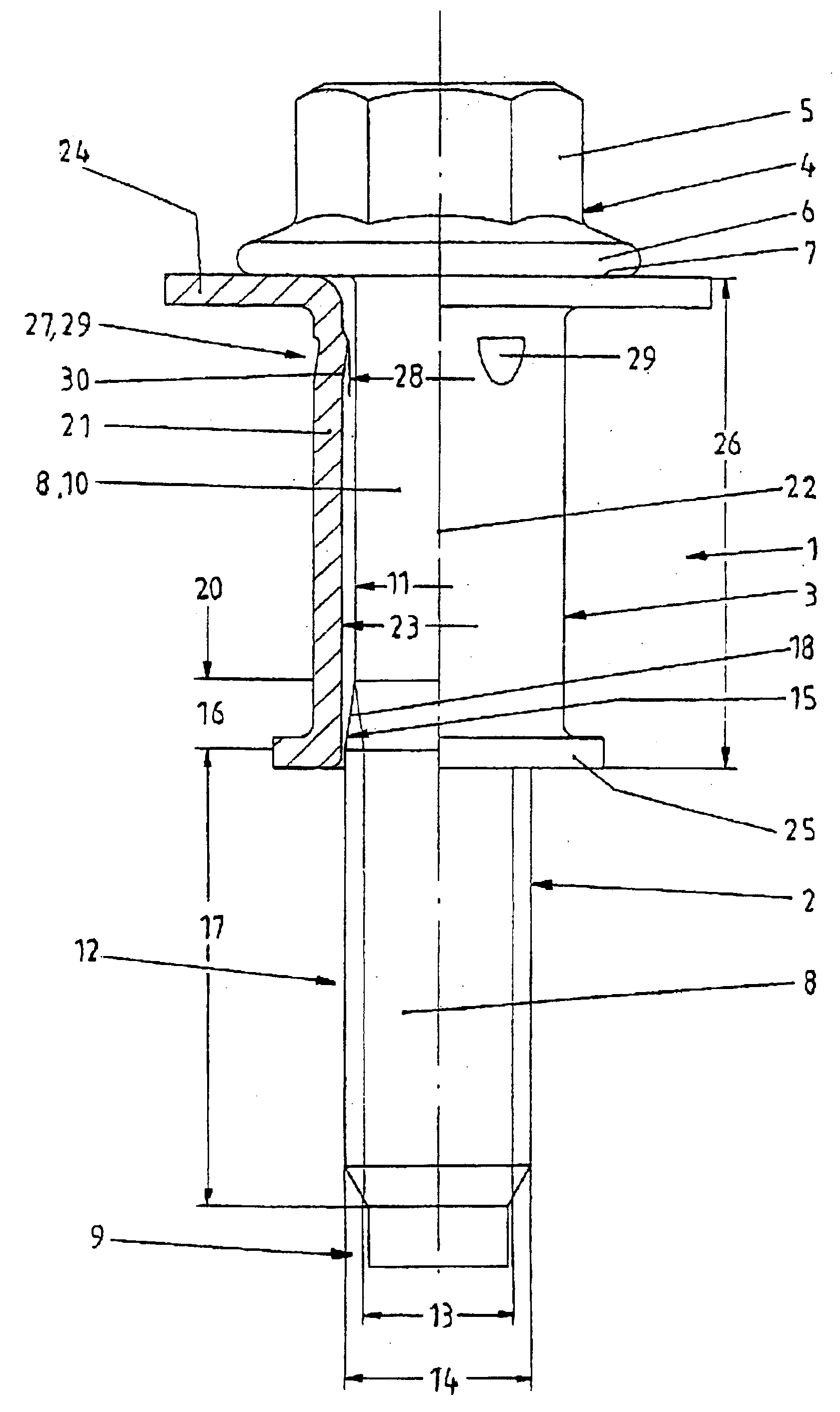
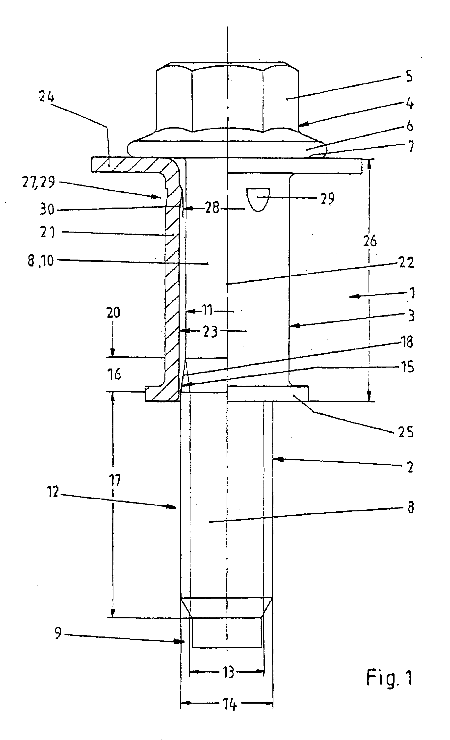
Referring now in greater detail to the drawings, FIG. 1 illustrates a first exemplary of the novel fastener 1. The fastener 1 or fastener assembly includes two or more components. Especially, it includes a screw 2 and a supporting element 3.

In the illustrated exemplary embodiment of the novel fastener 1, the screw 2 is designed as a collar screw. However, it may also have a different design. The screw 2 includes a head 4 including an engagement surface 5 for a torsional tool for operating the screw and a collar 6 including a supporting surface 7 serving to transmit an axial force onto a component (not illustrated). A shank 8 extends from the head 4 and from its supporting surface 7, respectively, to the free end 9 of the screw 2. The shank 8 in the region of the free end 9 may include a centering portion. The shank 8 at its side facing the head 4 includes a shank portion 10 having a diameter 11 which is less or smaller than the diameter of a thread to be described herein below.

A thr...


PUM


Abstract

A fastener (1) includes a screw (2) and a supporting element (3). The screw (2) includes a head (4), a shank (8) and a threaded portion (12). The threaded portion (12) is located on the shank (8). The threaded portion (12) includes a thread having an outer diameter (14). The threaded portion (12) includes a thread runout (25) facing the head (4) of the screw (2). The shank (8) includes a shank portion (10) having a diameter (11) which is smaller than the outer diameter (14) of the thread. The supporting element (3) is captively connected to the screw (2), and it includes at least one narrow location (27). The narrow location (27) has a diameter (28) which is smaller than the outer diameter (14) of the thread. The narrow location (27) includes at least one surface element (30, 35) facing the thread runout (25) and forming an enveloping cone (31) enveloping the thread runout (25) to prevent the supporting element (3) from getting clamped at the thread runout (25) of the screw (2).

Description

CROSS REFERENCE TO RELATED APPLICATIONSThis application claims priority to co-pending German Patent Application No. 102 15 883.5 entitled “Verbindungselement mit einer Schraube und einem daran unverliebar angeordneten Stützelement”, filed Apr. 11, 2002.FIELD OF THE INVENTIONThe present invention generally relates to a fastener including a screw and a supporting element. The supporting element is captively and rotatably connected to the screw. For example, the supporting element may be designed as a bush, a plain washer, and the like. The fastener includes at least these two elements being captively connected to one another. However, it may also include additional elements. The elements of the fastener are produced in series to attain a great prefabrication ratio, and to simplify and to accelerate assembly of the fasteners. Usually, the screw and the supporting element are both made of metal. However, it is also possible to design at least one of the two elements to be made of a diff...

Claims


Application Information

Patent Timeline
IPC IPC(8): F16B41/00
CPCF16B41/002Y10S411/999
Inventor DEEG, WOLFGANGFREIDHOF, GERHARDHOHL, JURGEN
Owner KAMAX HLDG
Why Eureka
Try Eureka