Method for producing electrical contacts using selective melting and a low pressure kinetic spray process

a technology of kinetic spray and selective melting, which is applied in the direction of molten spray coating, coating, plasma technique, etc., can solve the problems of fragments of original tin particles, broken particles, and rapid clogging of throats

Inactive Publication Date: 2005-03-29
DELPHI TECH INC
View PDF105 Cites 32 Cited by
  • Summary
  • Abstract
  • Description
  • Claims
  • Application Information

AI Technical Summary

Problems solved by technology

One difficulty that can arise is that with certain particles sizes the throat can rapidly become plugged.
It was found, however, upon subsequent bending of the coated substrates to form them into the required terminal shape the particles broke internally along these fracture lines and left a fragment of the original tin particle at the break on the substrate.
These broken particles negatively affect the substrate surface.

Method used


Image

  • Method for producing electrical contacts using selective melting and a low pressure kinetic spray process
  • Method for producing electrical contacts using selective melting and a low pressure kinetic spray process
  • Method for producing electrical contacts using selective melting and a low pressure kinetic spray process

Examples


Embodiment Construction

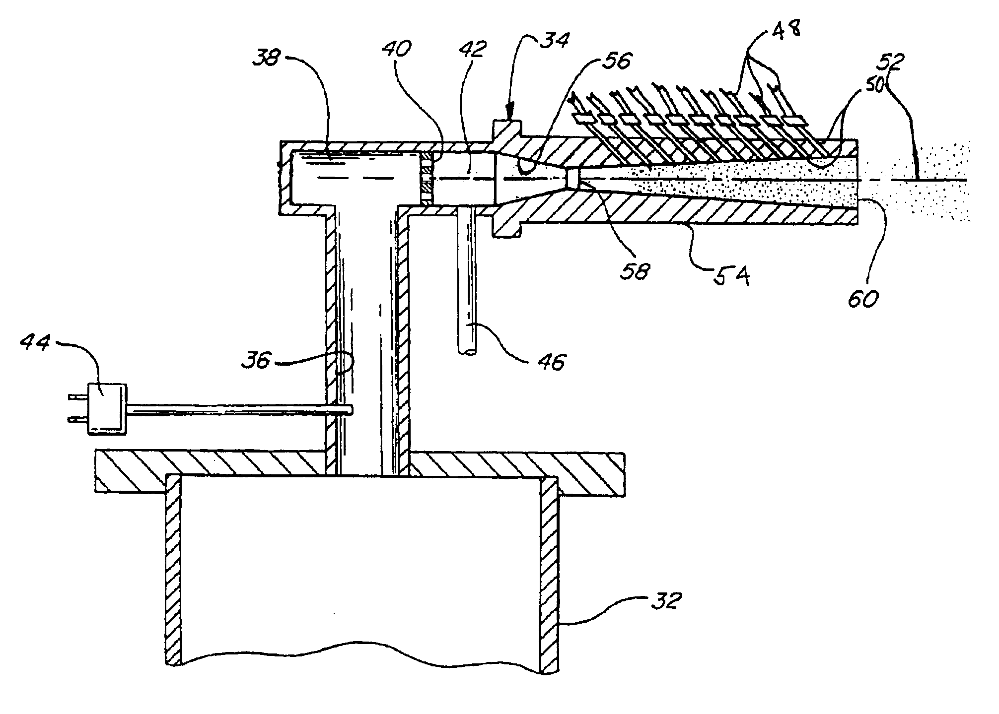
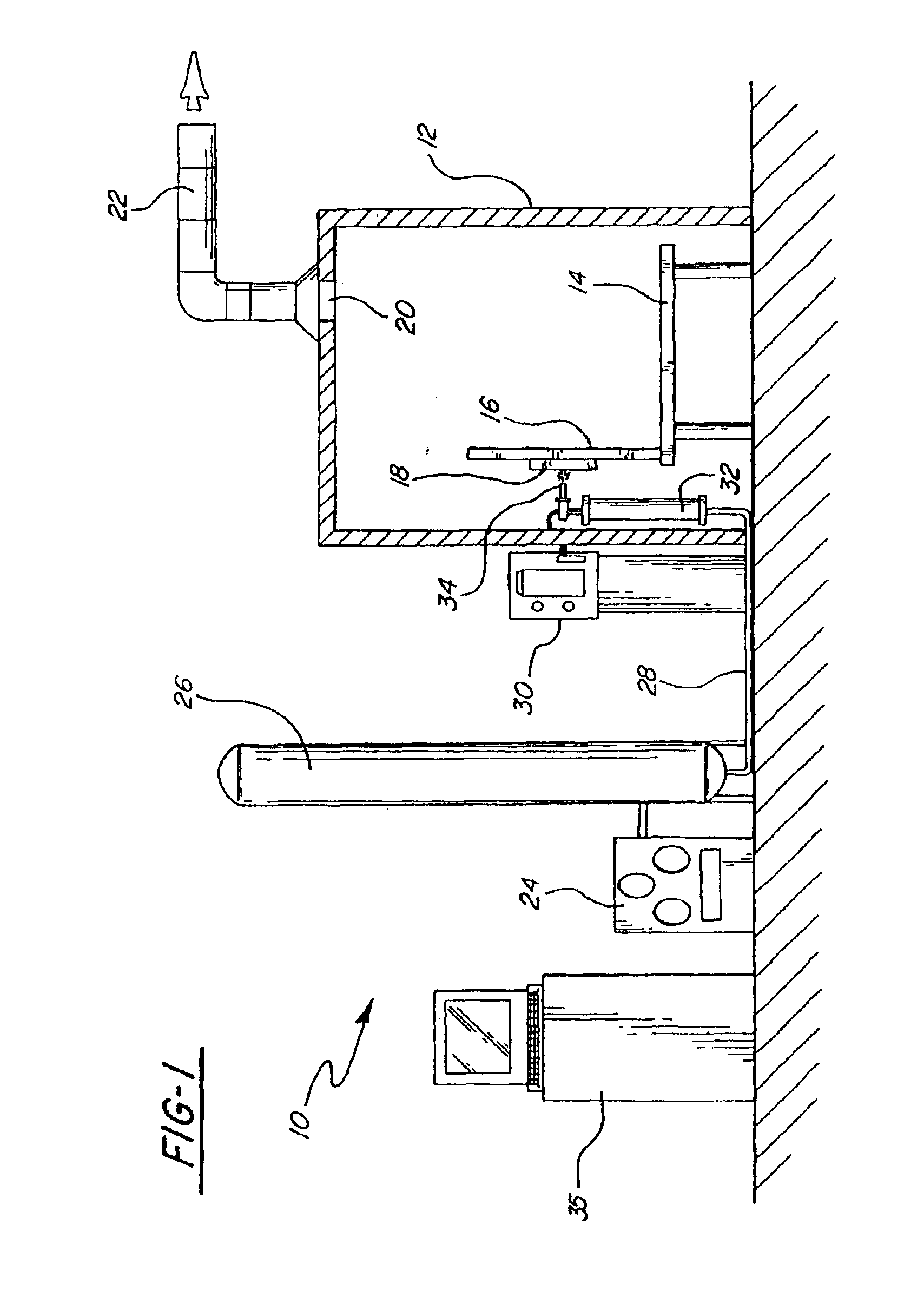
Referring first to FIG. 1, a kinetic spray system according to the present invention is generally shown at 10. System 10 includes an enclosure 12 in which a support table 14 or other support means is located. A mounting panel 16 fixed to the table 14 supports a work holder 18 capable of movement in three dimensions and able to support a suitable workpiece formed of a substrate material to be coated. The work holder 18 is preferably designed to feed a substrate material past a nozzle 34 at traverse speeds of from 20 to 400 feet / minute, more preferably at speeds of from 30 to 50 feet / minute. The enclosure 12 includes surrounding walls having at least one air inlet, not shown, and an air outlet 20 connected by a suitable exhaust conduit 22 to a dust collector, not shown. During coating operations, the dust collector continually draws air from the enclosure 12 and collects any dust or particles contained in the exhaust air for subsequent disposal.

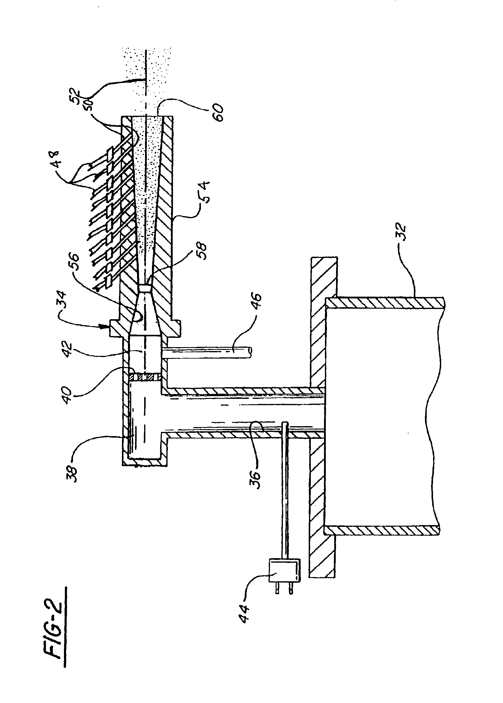
The spray system 10 further includes an ...


PUM

PropertyMeasurementUnit
temperatureaaaaaaaaaa
diameteraaaaaaaaaa
diameteraaaaaaaaaa

Abstract

A new kinetic spray process is disclosed that enables the coating to withstand severe bending and stress without delamination. The method includes use of a low pressure kinetic spray supersonic nozzle having a throat located between a converging region and a diverging region. A main gas temperature is raised to from 1000 to 1300 degrees Fahrenheit and the coating particles are directly injected into the diverging region of the nozzle at a point after the throat. The particles are entrained in the flow of the gas and accelerated to a velocity sufficient to result in partial melting of the particles upon impact on a substrate positioned opposite the nozzle and adherence of the particles to the substrate. The coating also has a desirable shinny surface. The method finds special application in coating substrates for use in formation of electrical connections.

Description

TECHNICAL FIELDThe present invention is directed toward a method for producing an electrical contact using a kinetic spray process, and more particularly, toward a method that includes selective melting of kinetically sprayed particles.INCORPORATION BY REFERENCEThe present invention comprises an improvement to the kinetic spray process as generally described in U.S. Pat. Nos. 6,139,913, 6,283,386 and the articles by Van Steenkiste, et al. entitled “Kinetic Spray Coatings” published in Surface and Coatings Technology Volume III, Pages 62-72, Jan. 10, 1999, and “Aluminum coatings via kinetic spray with relatively large powder particles”, published in Surface and Coatings Technology 154, pp. 237-252, 2002, all of which are herein incorporated by reference.BACKGROUND OF THE INVENTIONA new technique for producing coatings on a wide variety of substrate surfaces by kinetic spray, or cold gas dynamic spray, was recently reported in two articles by T. H. Van Steenkiste et al. The first was ...

Claims


Application Information

Patent Timeline
Patent Type & Authority Patents(United States)
IPC IPC(8): B05B7/14B05B7/16C23C24/04C23C24/00
CPCB05B7/1486C23C24/04B05B7/1626
Inventor VAN STEENKISTE, THOMAS HUBERTGORKIEWICZ, DANIEL WILLIAMDREW, GEORGE ALBERT
Owner DELPHI TECH INC
Why Eureka
Try Eureka