Double brush assembly

Inactive Publication Date: 2005-03-29
JOHNSON ELECTRIC INTERNATIONAL AG
View PDF11 Cites 12 Cited by
  • Summary
  • Abstract
  • Description
  • Claims
  • Application Information

AI Technical Summary

Benefits of technology

By use of the inventive brush assembly, the life of the motor can be extended with the expectant brush life increased up to double the previous life without increasing the radial width of the motor, although

Problems solved by technology

One drawback of using universal motors is that they have a wound rotor and use brushes rubbing on a commutator to transfer electrical energy to the rotor windings.
This introduces a life limitation.
The higher the power of the motor, the higher the current drawn and the faster the brushes wear.
For many small electric motors, the cost of replacing the brushes is prohibitive and most appliances come to the end of their useful life when the motor wears out.
As other parts of the motor have improved, the life limiting factor has become the lif

Method used


Image

  • Double brush assembly
  • Double brush assembly
  • Double brush assembly

Examples


Embodiment Construction

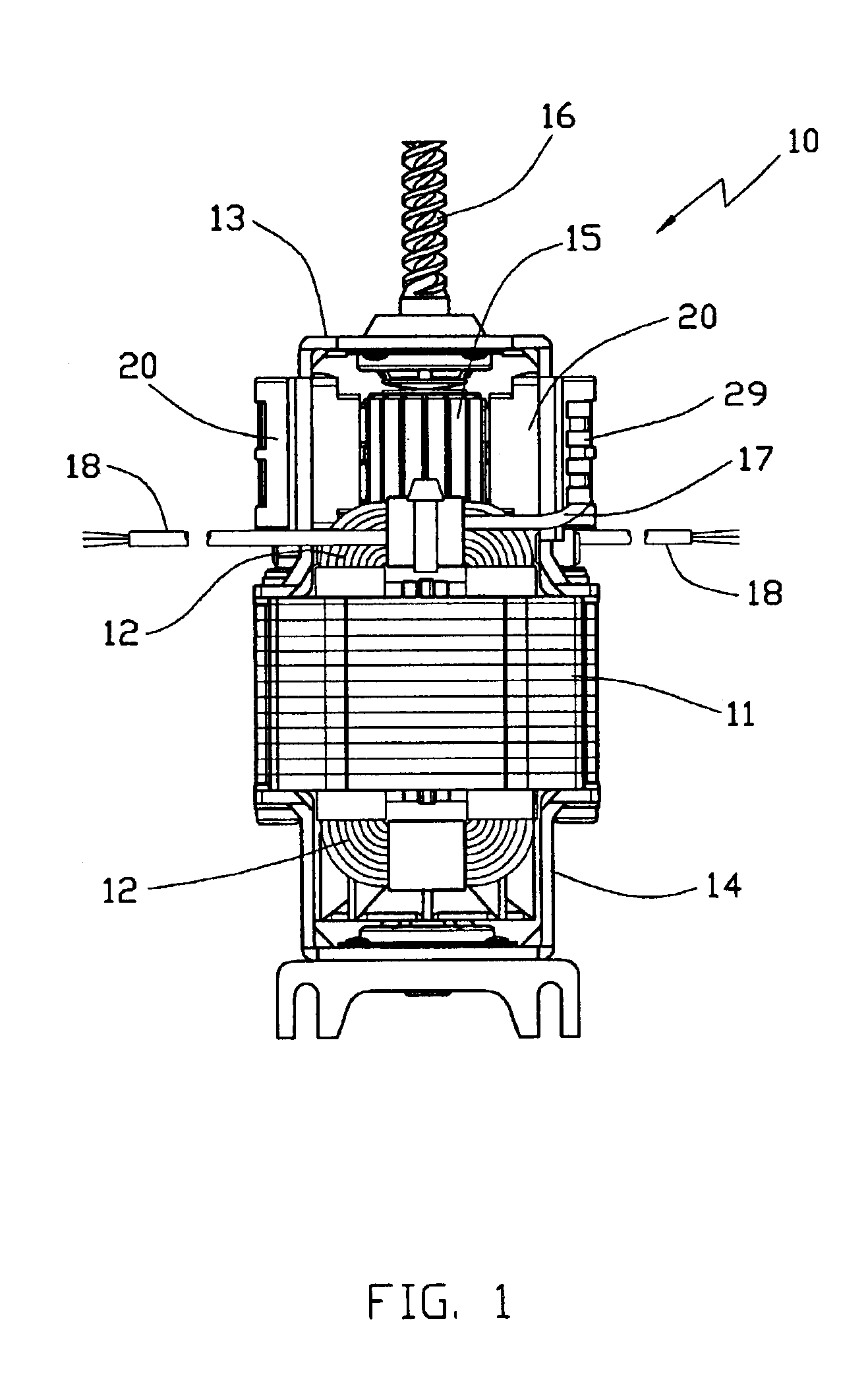
FIG. 1 illustrates a universal motor 10 which apart from the brush gear is of conventional construction. As such, it has a wound stator core 11 supporting stator windings 12 and end brackets 13, 14 which hold bearings. A wound rotor having a rotor core, rotor windings and a commutator 15 mounted on a shaft 16. The shaft 16 is journalled in the bearings. One end bracket 13 also supports the brush gear which comprises two brush assemblies 20. A lead 17 connects the stator windings to the brush assemblies and power leads 18 connect the stator windings to the electric supply.

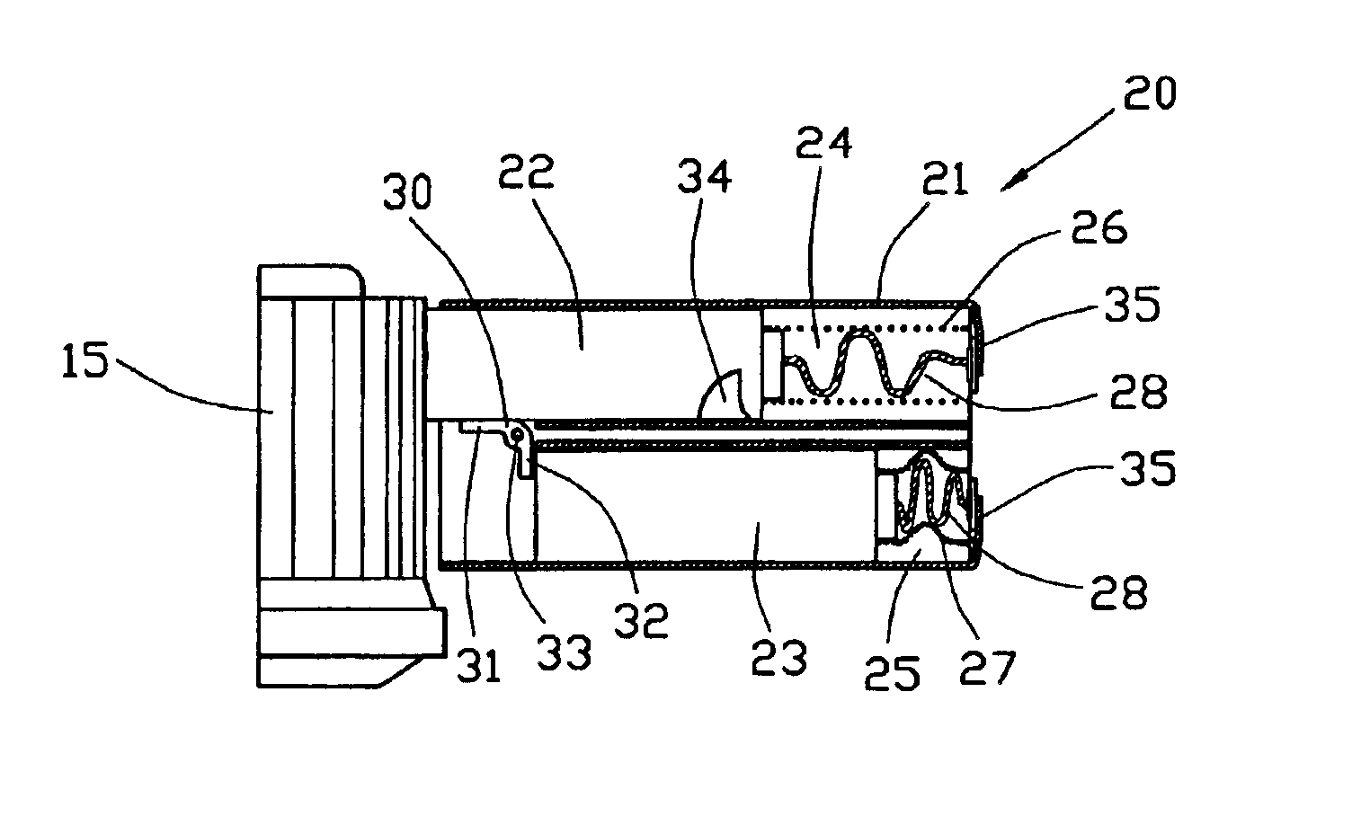
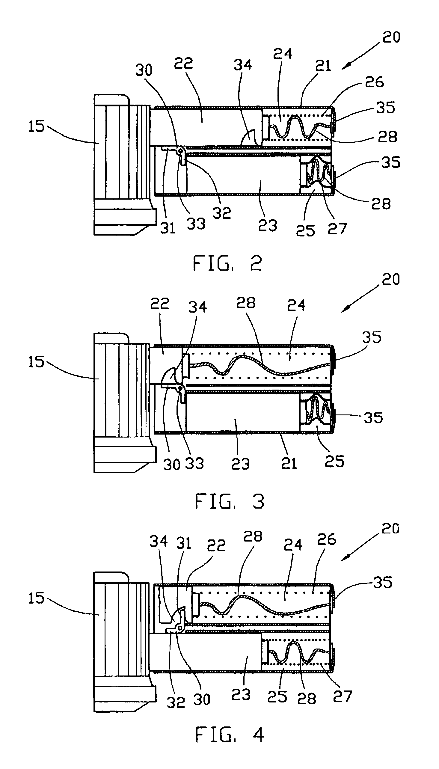
As the brush assemblies are identical, only one will be described. FIGS. 2-4 schematically illustrate the construction and operation of a brush assembly.

The brush assembly 20 has a cage 21 which guides first and second carbon brushes 22, 23 into contact with the commutator 15. Each brush 22, 23 is slidably received in a separate compartment 24, 25 and urged into contact with the commutator 15 by a spring 26, 27. Shu...


PUM


Abstract

A multi-brush cage assembly for a subfractional horsepower electric motor has two brushes 22, 23 received in separate chambers 24, 25 of the cage and urged by springs 26, 27 towards a commutator 15 of the motor. An L-shaped changeover lever 30 is located on a pivot 33 between the chambers and keeps one brush 23 retracted until the other brush 22 has worn out.

Description

This invention relates to subfractional horsepower electric motors of the universal type and in particular, to a cage brush assembly for such motors.Universal motors have many uses and are commonly used in household appliances. One drawback of using universal motors is that they have a wound rotor and use brushes rubbing on a commutator to transfer electrical energy to the rotor windings. This introduces a life limitation. The higher the power of the motor, the higher the current drawn and the faster the brushes wear. For many small electric motors, the cost of replacing the brushes is prohibitive and most appliances come to the end of their useful life when the motor wears out. However, many appliance manufacturers would like to guarantee their appliances to run for so many hours and this has become an important marketing advantage. As other parts of the motor have improved, the life limiting factor has become the life of the brushes. While the life can be increased by brush compos...

Claims


Application Information

Patent Timeline
IPC IPC(8): H02K5/14H01R39/00H01R39/38H01R39/44
CPCH01R39/381H02K5/148H02K2205/06H01R39/44
Inventor KO, FRETRICK SIU KWANMAN, YIU LEUNG
Owner JOHNSON ELECTRIC INTERNATIONAL AG
Why Eureka
Try Eureka