Stationary armature machine

a technology of armature machine and armature body, which is applied in the direction of current collector, dynamo-electric machine, electrical apparatus, etc., can solve the problems that the conventional dc brush type motor cannot meet the demands of hybrid vehicles and appliances, and achieve the effect of increasing current carrying capacity, increasing heat absorption, and increasing current carrying capacity

Inactive Publication Date: 2005-03-29
RICHARD DOUGLAS ODELL
View PDF3 Cites 11 Cited by
  • Summary
  • Abstract
  • Description
  • Claims
  • Application Information

AI Technical Summary

Problems solved by technology

Conventional DC brush type motors are unable to meet the demands of hybrid vehicles and appliances that required large amounts of power and operate at high rotating speeds such as leaf blowers and upright vacuum cleaners because of size, volume or weight constraints.

Method used


Image

  • Stationary armature machine
  • Stationary armature machine
  • Stationary armature machine

Examples


Embodiment Construction

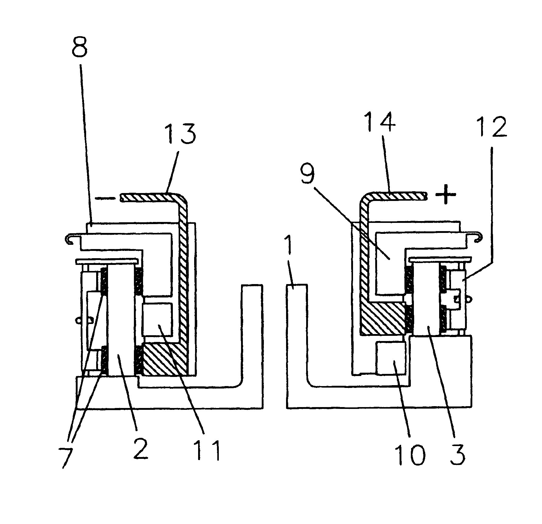
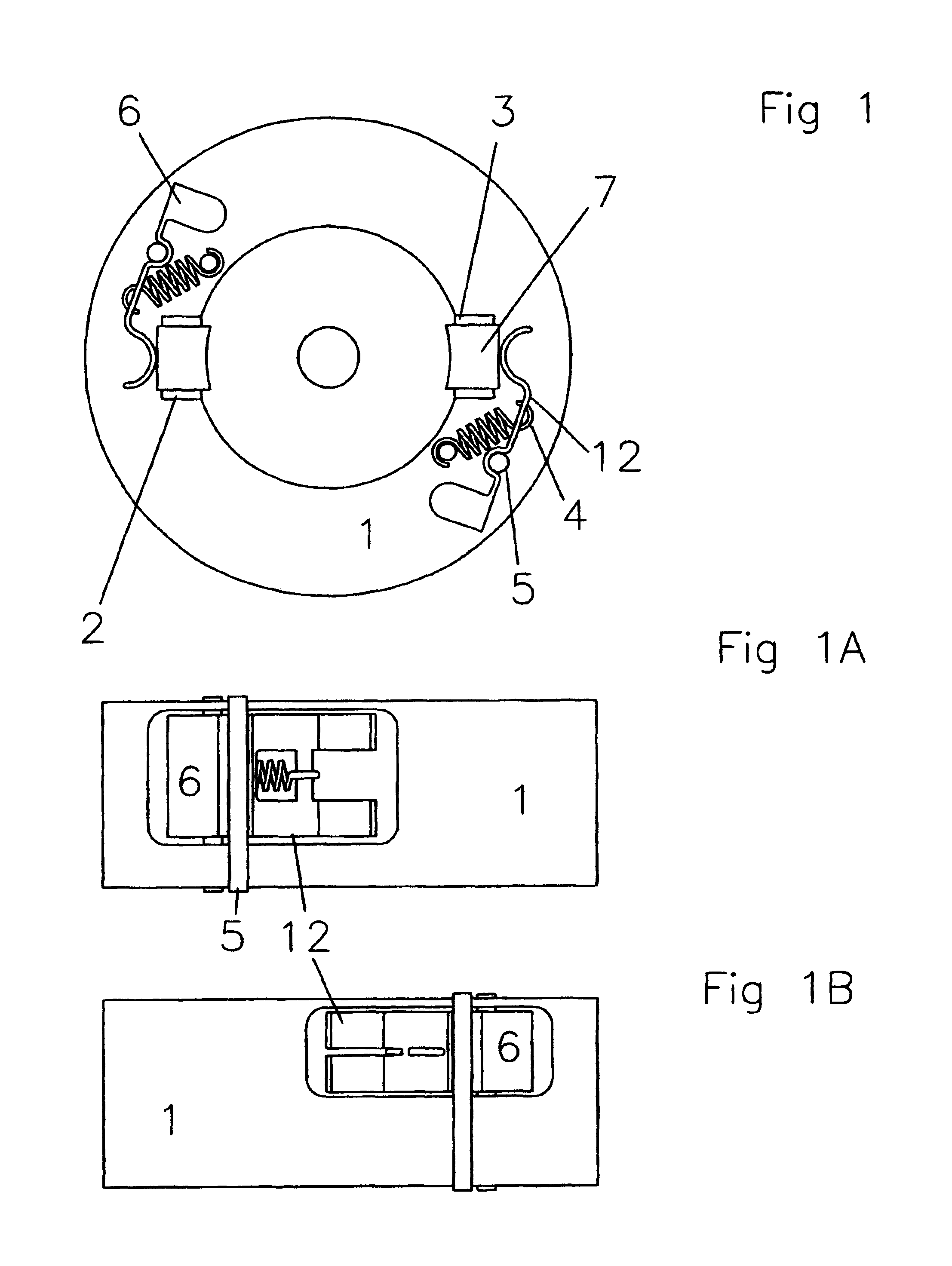
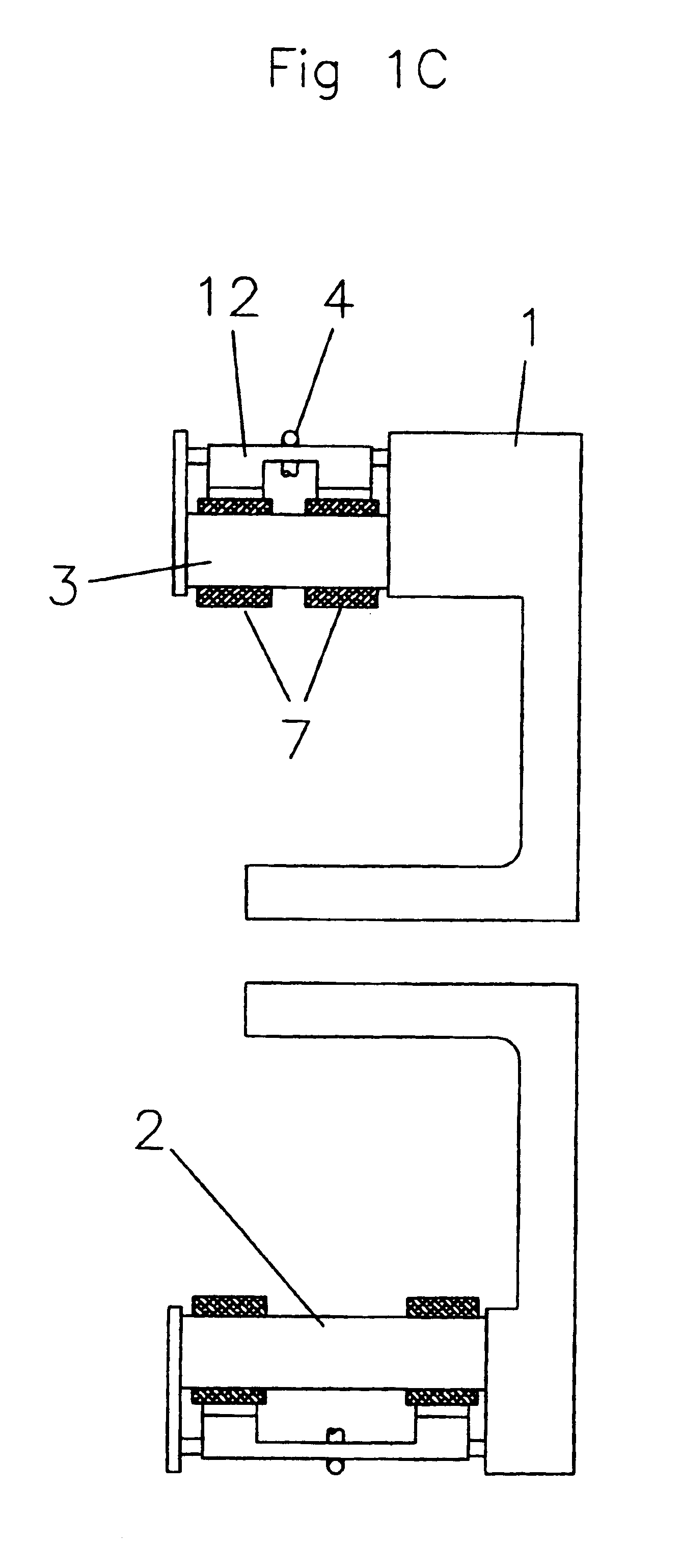
FIG. 1 shows the front view of a 2-pole rotating brush assembly as a means for conducting electric current from a power supply to the armature windings and field coils. FIG. 1-1 shows the front view of the rotating brush assembly housing capable of providing physical support and electrical isolation of the attached components. FIG. 1-2 shows a negative polarity copper brush holder attached to FIG. 1-1 as a means for guiding said brush and providing additional electric current shunting capacity. FIG. 1-3 shows a positive polarity copper brush holder as a means for guiding said brush and providing additional electric current shunting capacity.

FIG. 1-4 shows a spring as a means for keeping said brush in contact with said commutator. FIG. 1-5 shows the fulcrum of the brush keeper as a means for supporting said brush keeper and as means for providing a moment opposite that applied from centrifugal forces acting on said brush. FIG. 1-6 shows the counter weight portion of FIG. 1-12 as a me...


PUM


Abstract

The Stationary Armature Machine (SAM) comprised of a stationary armature, a stationary commutator affixed to the frame or housing and a rotating field and brushes affixed to a common shaft as a means for mechanical commutation of electrical currents based on Lorentz' force law. SAM's unique stationary armature increases current carrying capacity and heat abatement at low voltages and high rotating speeds without increasing overall physical size relative to BLDC motors. SAM's armature and field structure are arranged in reverse having the armature in a stationary position with a commutation assembly affixed to the machine's housing while said field structure (and brush assembly) rotate at the center of the machine. By making the armature and commutator assembly stationary, the current carrying conductors can be made much larger without being subjected to extreme centrifugal forces at high rotating velocities. SAM is ideally suited for applications that require high torque and power at high rotational speeds in a small inexpensive package.

Description

BACKGROUND OF INVENTIONConventional Brush Type DC Electric Motors have been used for many years in power tools, electric scooters & vehicles, appliances and other assorted machinery. The main parts are comprised of an a field structure, yoke or housing and brush rigging. The armature being the rotating part of the motor consists of a laminated steel core having slots as a means for holding coils of wire electrically connected to a commutator affixed to a common shaft. Electrical current from a power source flows through stationary magnetic field coils and brushes affixed to a housing and through annature windings affixed to a rotor as a means for generating a rotating magnetic field magnetic wave that drives the rotor. This arrangement generates a large amount of heat at the center of the motor having limited means for heat abatement through the air gap, field structure and housing such that direct current brush type motors are much larger than ac motors (and BLDC) of the same power...

Claims


Application Information

Patent Timeline
Patent Type & Authority Patents(United States)
IPC IPC(8): H02K23/62
CPCH02K23/62
Inventor RICHARD, DOUGLAS ODELL
Owner RICHARD DOUGLAS ODELL
Why Eureka
Try Eureka