
Ignition coil

Active Publication Date: 2005-03-29
DENSO CORP
View PDF11 Cites 4 Cited by
  • Summary
  • Abstract
  • Description
  • Claims
  • Application Information

AI Technical Summary

Benefits of technology

According to the ignition coil of the present invention, the resin insulating material is in a solid state. This simplifies the sealing mechanism when compared with the electrically insulating oil used for insulation. Furthermore, according to the ignition coil of the present invention, the members to be accommodated in the igniter are covered with a single layer of the resin insulating material. For this reason, an additional step of encapsulating the members accommodated in the igniter in a molding resin is not necessary upon fabricating the ignition coil.
Therefore, according to the present invention, it is possible to provide an ignition coil that can be fabricated at low costs in a simple structure and reduced in size. Additionally, further areas of applicability of the present invention will become apparent from the detailed description provided hereinafter. It should be understood that the detailed description and specific examples, while indicating the preferred embodiment of the invention, are intended for purposes of illustration only and are not intended to limit the scope of the invention.

Problems solved by technology

This causes an increase in complexity of the structure of the ignition coil due to the sealing mechanism.
This also causes an increase in the size of the ignition coil.
This further causes an increase in manufacturing costs.
Accordingly, this increases the complexity of the fabrication process.
This also causes an increase in manufacturing costs.
This further causes an increase in complexity of the structure of the ignition coil due to the provision of the double resin layers.

Method used


Image

  • Ignition coil
  • Ignition coil
  • Ignition coil

Examples


first embodiment

(1) First Embodiment

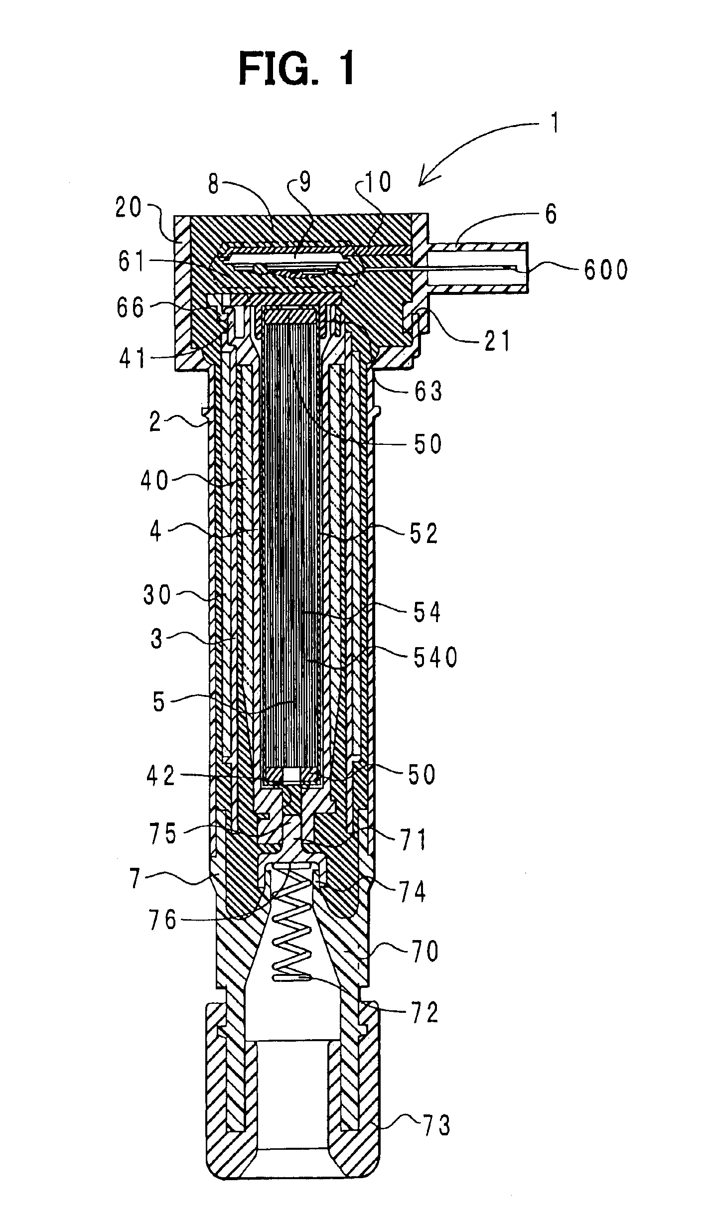
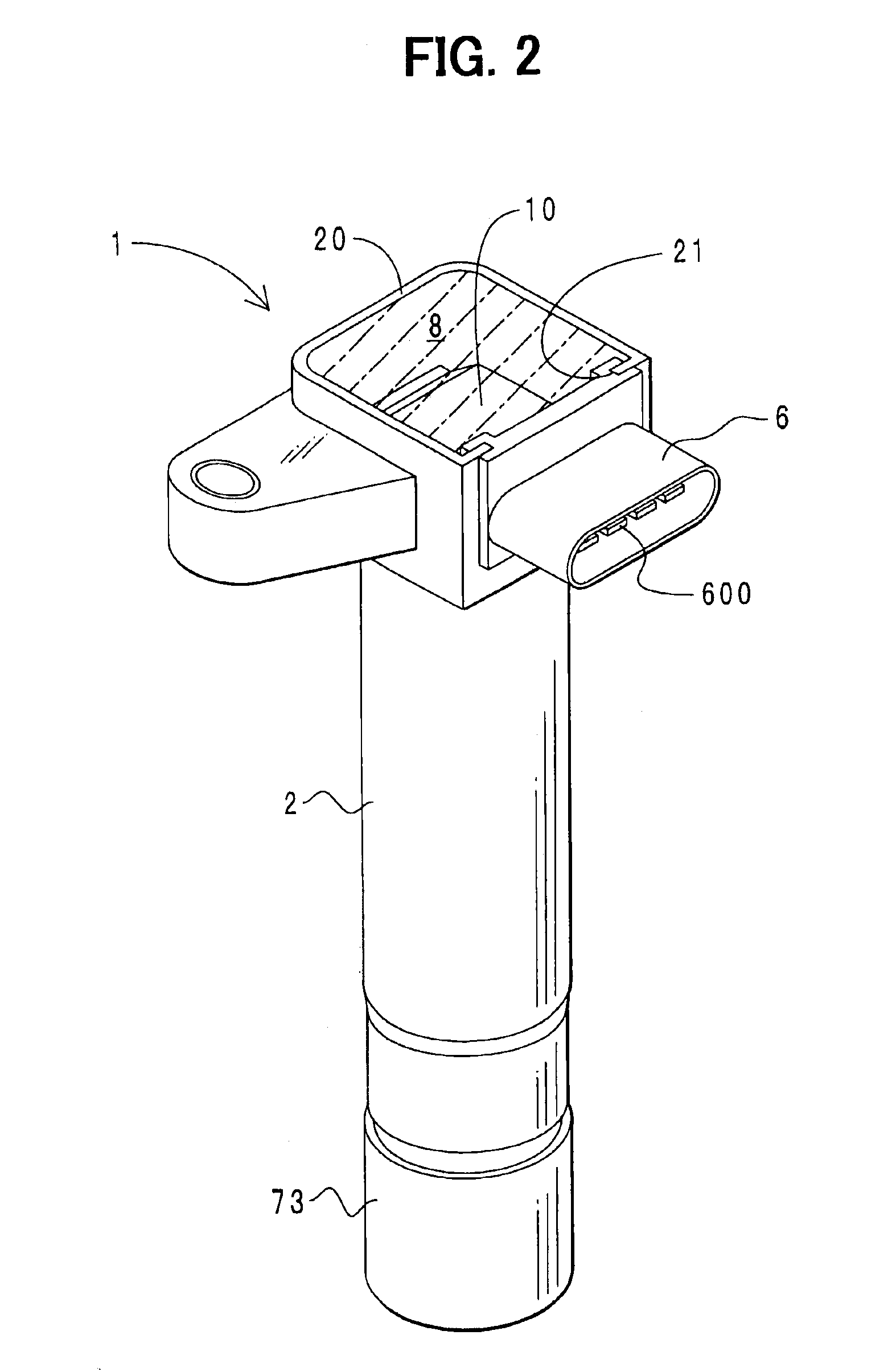
The structure of the ignition coil according to this embodiment will first be described. FIG. 1 is an axial cross-sectional view showing the ignition coil according to this embodiment. FIG. 2 is an external view showing the ignition coil according to this embodiment. FIG. 2 is a view showing components through an epoxy resin. An ignition coil 1 of a stick type is accommodated in a plughole (not shown) formed in each cylinder on the upper portion of an engine block. As will be described later, the ignition coil 1 is connected to an ignition plug (not shown) at a lower side in the figure.

The ignition coil 1 comprises a housing 2. The housing 2 is made of a resin and takes the shape of a cylinder with a shoulder that is increased in diameter at an upper end. The portion below the shoulder is cylindrically shaped. On the other hand, the portion above the shoulder is rectangular shaped. Additionally, there is formed a wide opening 20 on the upper end portion of the ho...

second embodiment

(2) Second Embodiment

This embodiment differs from the first embodiment in that the positioning means is secured to the housing, and as well the connector and the igniter are not handled in one piece. Accordingly, the description here will be made only with respect to the differences.

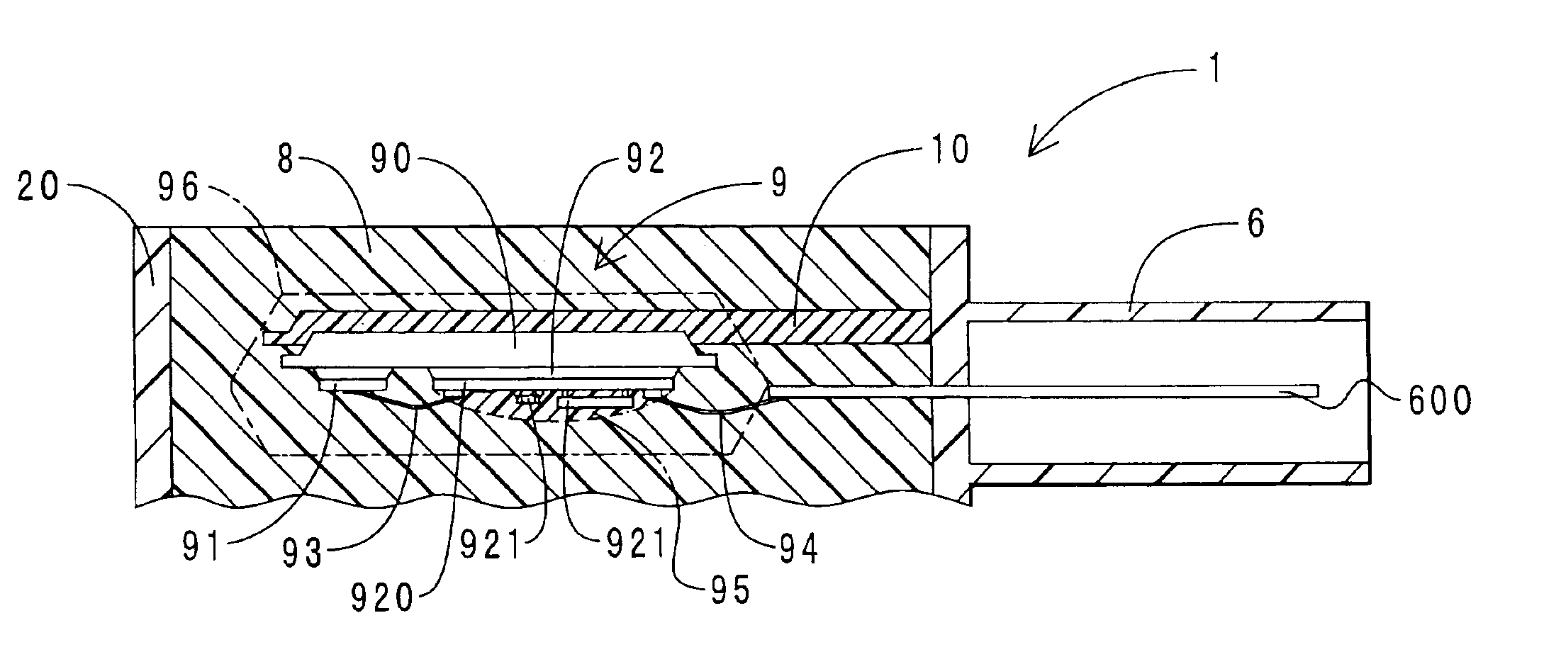
FIG. 6 is an enlarged cross-sectional view showing the vicinity of the igniter in the ignition coil according to this embodiment. The components corresponding to those of FIG. 3 are indicated with the same symbols. As shown, positioning means 12 is secured to the wide opening 20 of the housing. The upwardly-oriented concave portion 11 is formed on the upper surface of the positioning means 12. The heat sink 90 of the igniter 9 is press fit from above into the concave portion 11. That is, the igniter 9 and the positioning means 12 of this embodiment are placed upside down with respect to those of the first embodiment.

The ignition coil 1 of this embodiment is assembled in the following steps. First, the me...

third embodiment

(3) Third Embodiment

This embodiment differs from the first embodiment in that the present invention is embodied in an ignition coil other than one of the stick type. Accordingly, the description here will be made only on the differences.

FIG. 7 is an axial cross-sectional view showing the ignition coil of this embodiment. In FIGS. 1 and 3, the same components are indicated with the same symbols. The ignition coil 1 comprises the housing 2 made of a resin. There are cores 55, a primary spool (not shown), a primary coil portion (not shown), the secondary spool 4, the secondary coil portion 40, the joint member 10, the high-voltage terminal 71, and a partition plate 22, each of which are accommodated inside the housing 2.

The core 55 takes the shape of an oval in cross section with the “C”-shaped cores being assembled together. The primary spool is made of a resin and is prismatic in shape. The primary spool is placed on the outer circumference side of the core 55. The primary coil porti...


PUM


Abstract

An ignition coil has a connector electrically connected to an external circuit, an igniter for accommodating a switching element adapted to cause a current supplied from the connector to be intermittent, a primary coil portion for generating a predetermined voltage by the intermittent current, a secondary coil portion for stepping up the generated voltage and applying the resulting voltage to an ignition plug, and a resin insulating material which hardens in between the primary coil portion and the secondary coil portion to ensure insulation between the primary coil portion and the secondary coil portion. An outer shell of the igniter is formed of the resin insulating material.

Description

CROSS REFERENCE TO RELATED APPLICATIONThis application is based upon, claims the benefit of priority of, and incorporates by reference, the contents of Japanese Patent Application No. 2002-159747 filed May 31, 2002.BACKGROUND OF THE INVENTION1. Technical Field of the InventionThe present invention relates to ignition coils, and more particularly, to an ignition coil which incorporates an igniter to apply a high voltage to an ignition plug.2. Description of Related ArtFor example, as an ignition coil of the type incorporating an igniter, an ignition coil which employs electrically insulating oil to ensure insulation is introduced in Japanese Patent Laid-Open Publication No. Hei 7-153636. A circuit module containing a power transistor, a primary coil portion, a secondary coil portion, and the like are accommodated inside the housing of the ignition coil in the publication. The housing also has a liquid electrical insulating oil injected therein. The electrical insulating oil ensures i...

Claims


Application Information

Patent Timeline
IPC IPC(8): F02P3/02H01F38/00H01F38/12H01F27/02H01F27/40H01F27/00
CPCF02P3/02H01F38/12H01F27/022F02D2400/18F02D2400/22H01F2038/125H01F27/40H01F41/005
Inventor KONDO, MASAHIROOSUKA, KAZUTOYOTAKEDA, SHUNICHI
Owner DENSO CORP
Features
  • Generate Ideas
  • Intellectual Property
  • Life Sciences
  • Materials
  • Tech Scout
  • Unparalleled Data Quality
  • Higher Quality Content
  • 60% Fewer Hallucinations
Learn More