

Electrophoretic display device and method for driving the same
a display device and electrophoretic technology, applied in the field of display techniques, can solve the problems of eye fatigue, characters are difficult to read in such a case, and characters presented on the screen are sometimes difficult to view depending on the display
- Summary
- Abstract
- Description
- Claims
- Application Information
AI Technical Summary
Benefits of technology
Problems solved by technology
Method used
Image

Examples
first embodiment
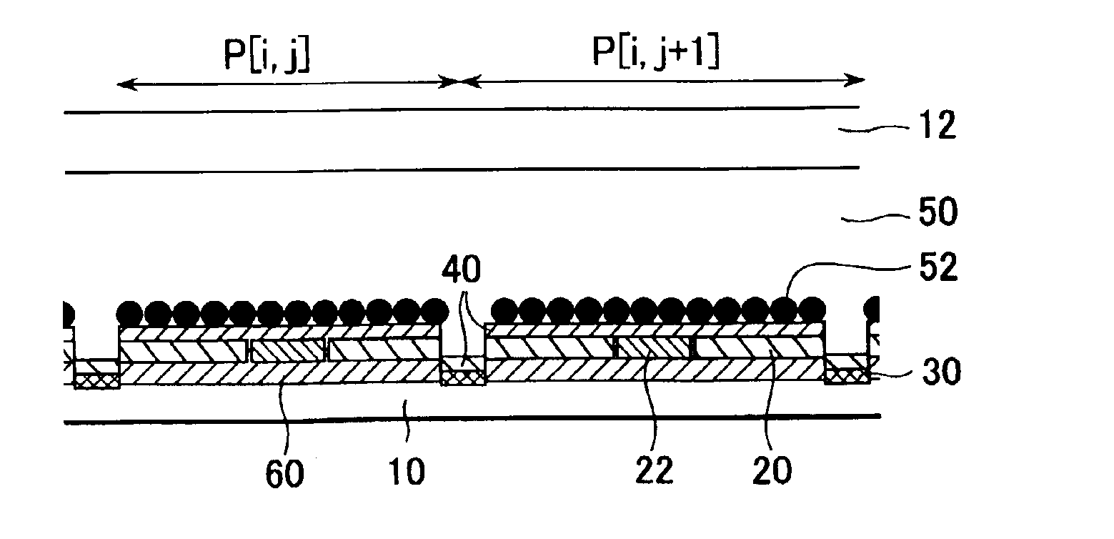
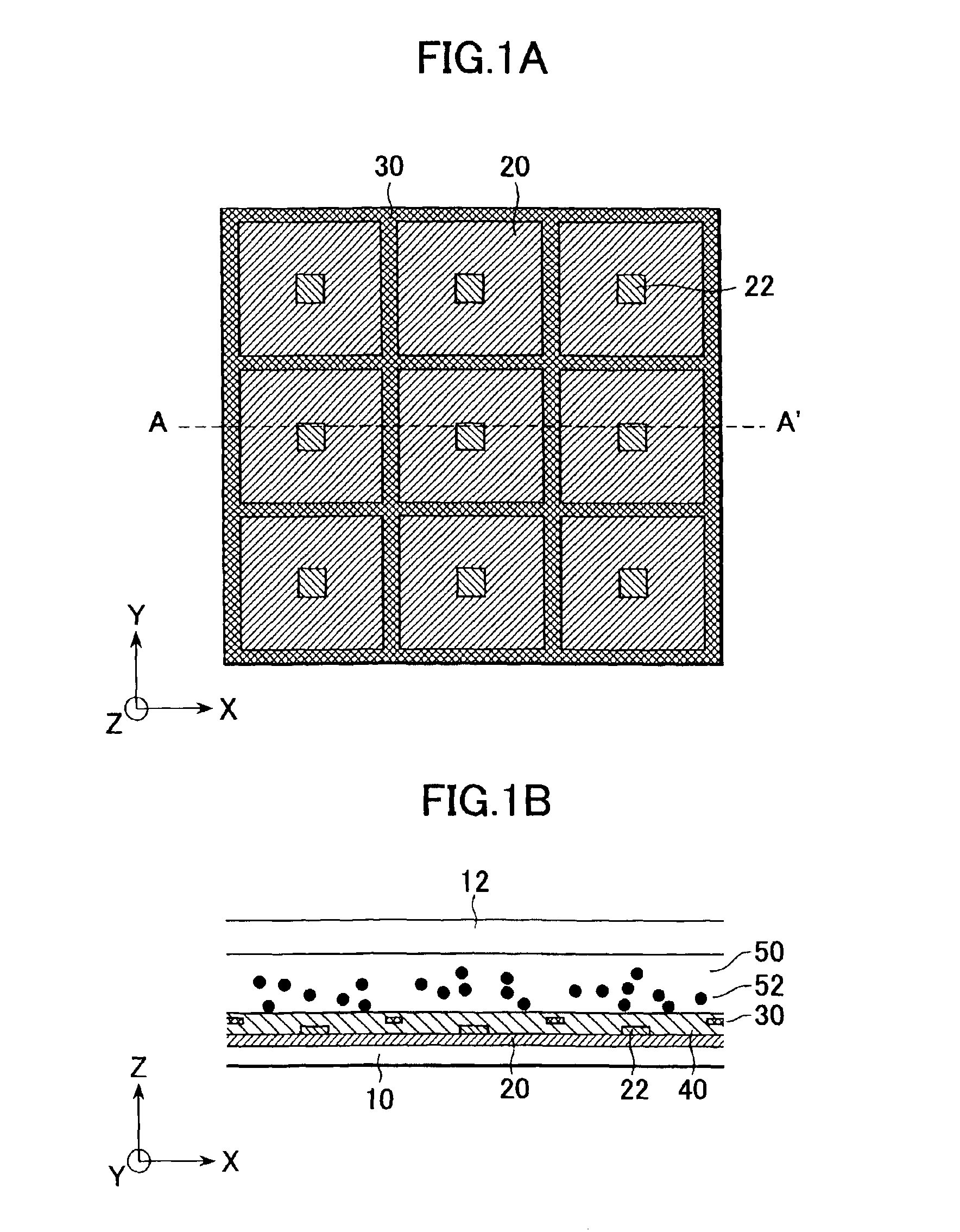
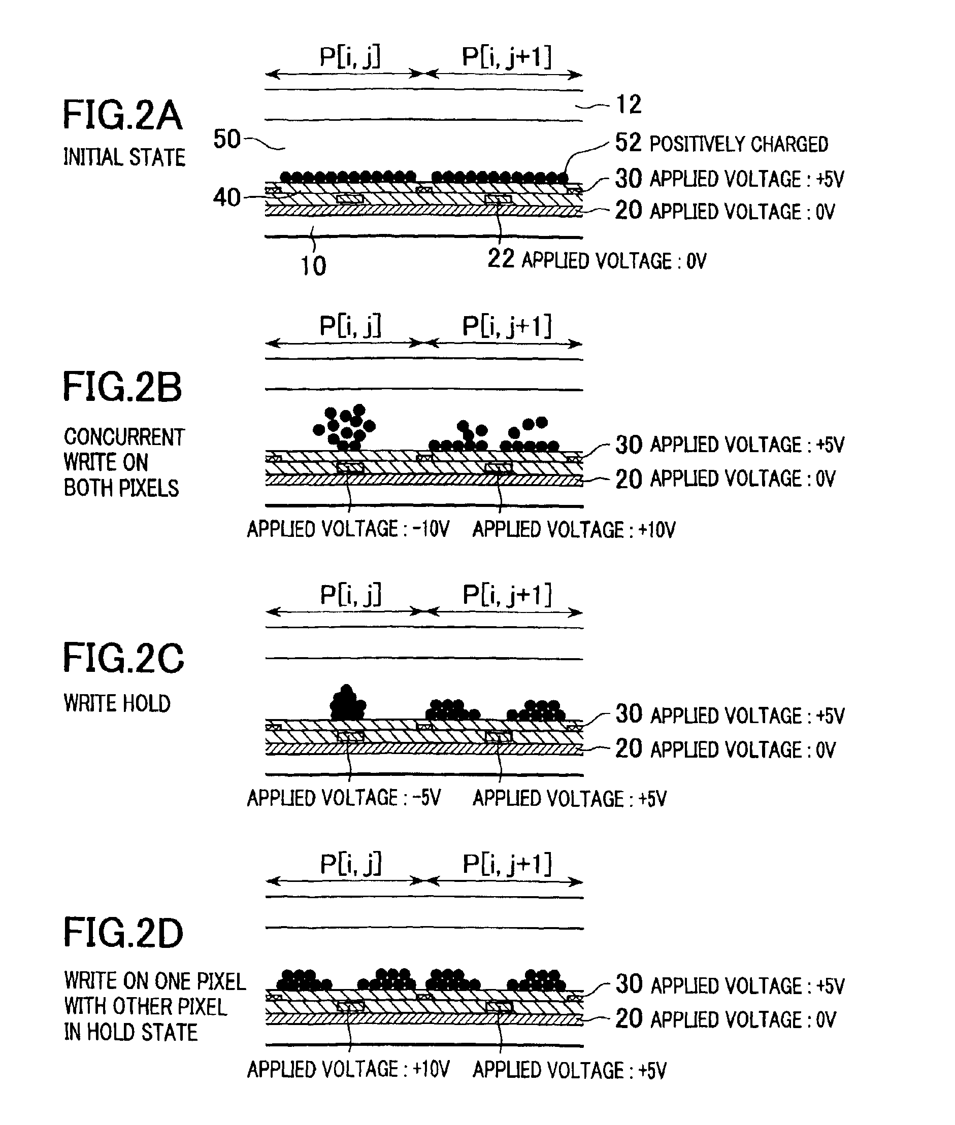
The display device of the present invention is discussed with reference to FIGS. 1A-2D. The electrophoretic display device of the present invention illustrated in FIGS. 1A and 1B includes a first substrate 10 and a second substrate 12 with a predetermined gap permitted therebetween in the Z direction, first display electrodes 20 and second display electrodes 22 for supplying the first substrate 10 with different voltages, a dispersing fluid 50 sandwiched between the two substrates 10 and 12, and a plurality of charged color particles 52 dispersed in the dispersing fluid 50. Silicone oil is used for the dispersing fluid 50 and a mixture of polystyrene and carbon and having a diameter of 1 to 2 μm is used for the charged particles 52.
The first display electrode 20 is produced by patterning an ITO (Indium Tin Oxide) film having a thickness of 100 nm arranged on a PET layer having a thickness of 300 μm. An ITO film having a thickness of 100 nm is disposed for the second display electrod...
second embodiment
A display device of the present invention is discussed below with reference to FIGS. 4A-5D. FIG. 4A is a top view of the electrophoretic display device of a second embodiment, and FIG. 4B is a sectional view taken along line A-A′ in FIG. 4A. The electrophoretic display device of the present invention includes a first substrate 10 and a second substrate 12 with a predetermined gap permitted therebetween in the Z direction, first display electrodes 20 and second display electrodes 22 for supplying the first substrate 10 with different voltages, a dispersing fluid 50 sandwiched between the two substrates 10 and 12, and a plurality of charged color particles 52 dispersed in the dispersing fluid 50. Silicone oil is used for the dispersing fluid 50 and a mixture of polystyrene and carbon and having a diameter of 1 to 2 μm is used for the charged particles 52.
The first display electrode 20 is produced by patterning an ITO film having a thickness of 100 nm arranged on a PET layer having a t...
third embodiment
A display device of the present invention will now be discussed with reference to FIG. 6. The electrophoretic display device of the present invention shown in FIG. 6 includes a first substrate 10 and a second substrate 12 with a predetermined gap permitted therebetween in the Z direction, first display electrodes 20 and second display electrodes 22 for supplying the first substrate 10 with different voltages, a guard electrode 30 in the border between pixels, and an electric shield electrode 32, disposed between the guard electrode 30 and one of the substrates bearing the guard electrode 30, for localizing the electric field generated by the guard electrode 30 to within a predetermined area. The electrophoretic display device further includes a dispersing fluid 50 sandwiched between the two substrates 10 and 12, and a plurality of charged color particles 52 dispersed in the dispersing fluid 50. Silicone oil is used for the dispersing fluid 50 and a mixture of polystyrene and carbon ...
PUM
| Property | Measurement | Unit |
|---|---|---|
| applied voltages | aaaaa | aaaaa |
| applied voltages | aaaaa | aaaaa |
| applied voltages | aaaaa | aaaaa |
Abstract
Description
Claims
Application Information