Method for detecting rotational speed

a technology of rotational speed and speed detection, which is applied in the direction of instruments, electrical control, force/torque/work measurement apparatus, etc., can solve the problems of shortening the sector or a smaller number of teeth entail too large errors, and speed information is not as curren

Inactive Publication Date: 2005-03-29
SIEMENS AG
View PDF7 Cites 10 Cited by
  • Summary
  • Abstract
  • Description
  • Claims
  • Application Information

AI Technical Summary

Benefits of technology

The object of the invention is therefore to specify a method of detecting the speed in an internal combustion engine...

Problems solved by technology

The scanning of shorter sectors or of a smaller number of teeth would entail too large an error on account of the abovementioned periodic oscillations.
However, on account of the averaging over a working stroke, i.e. an ...

Method used


Image

  • Method for detecting rotational speed
  • Method for detecting rotational speed
  • Method for detecting rotational speed

Examples


Embodiment Construction

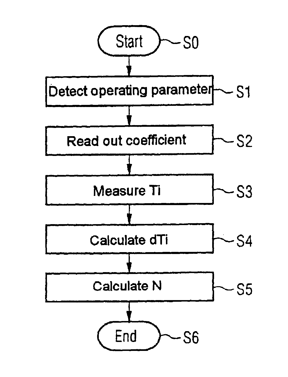
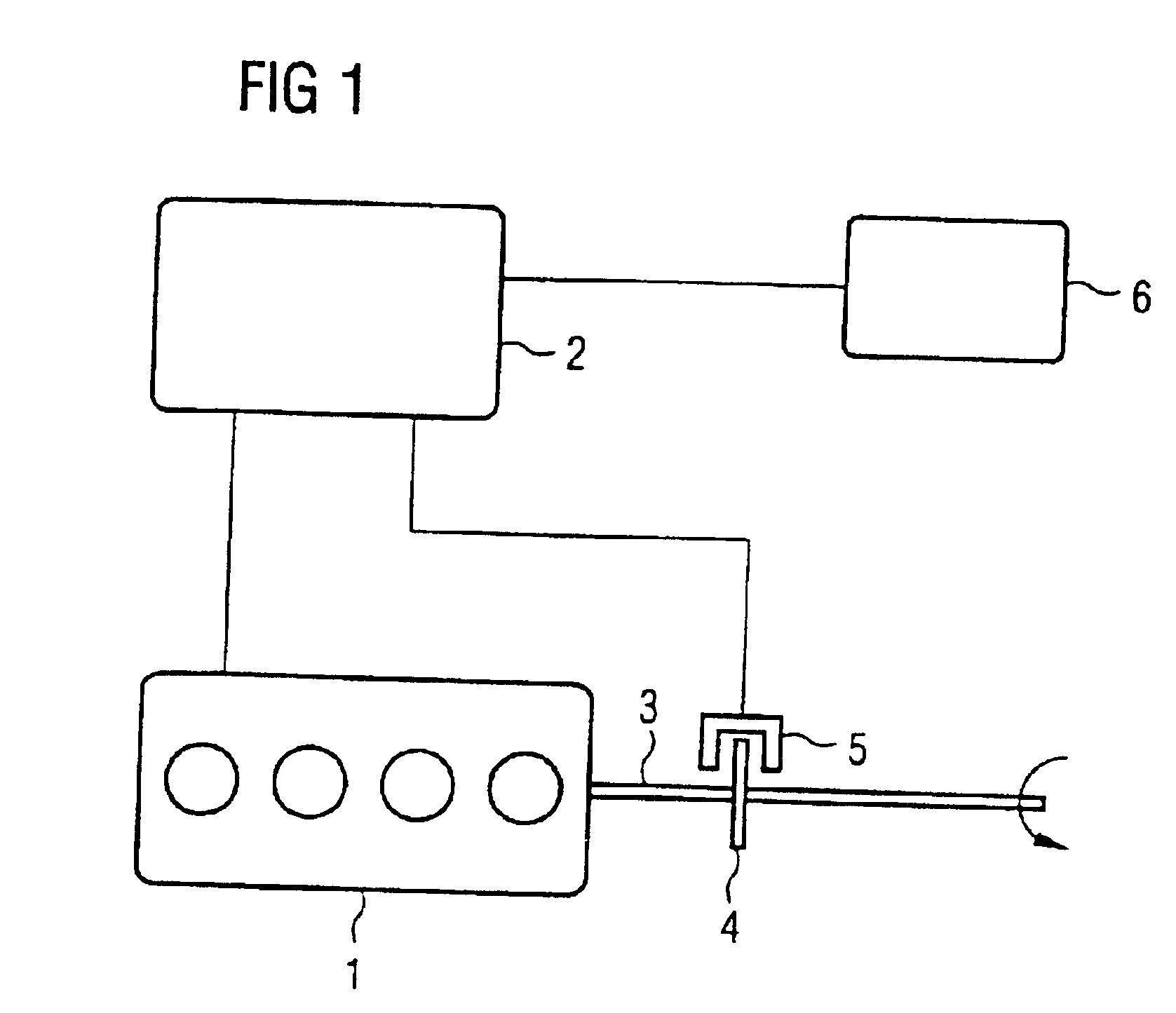
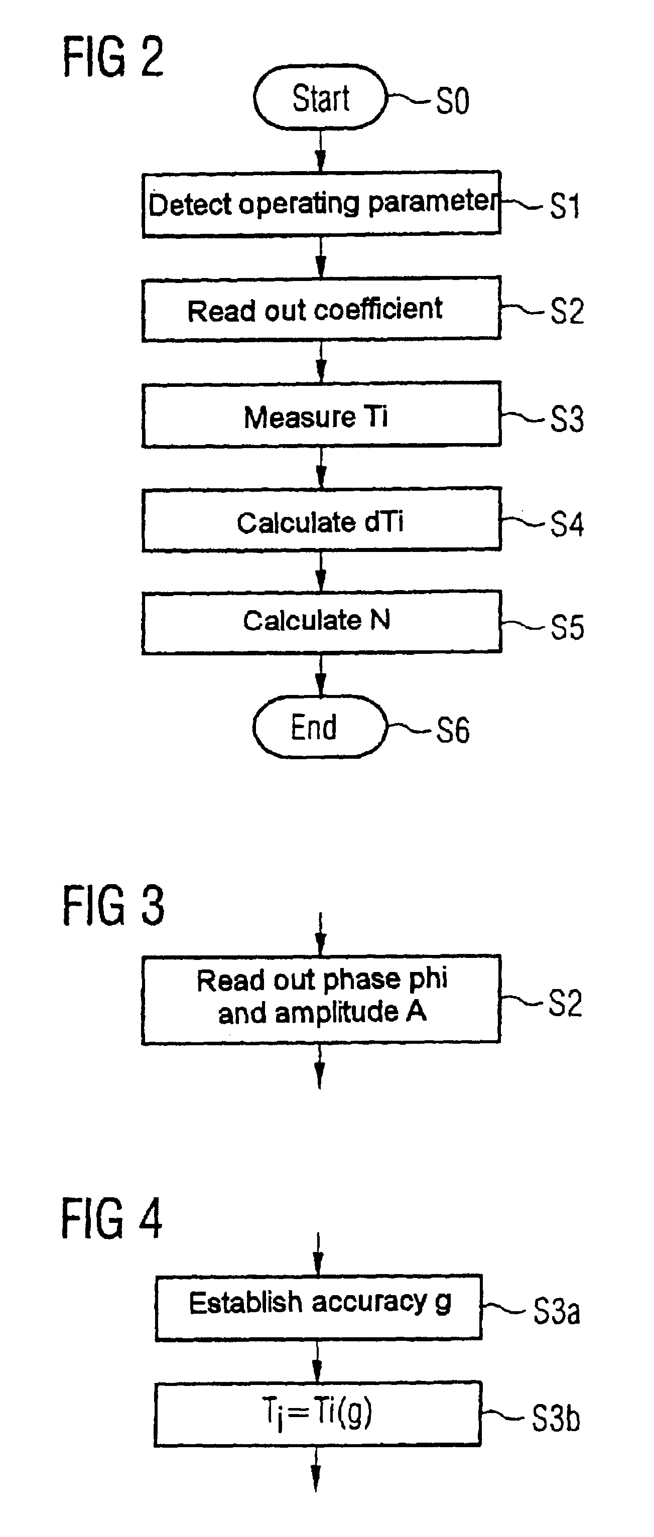
Shown schematically in FIG. 1 is an internal combustion engine 1, the operation of which is controlled by a control unit 2 via lines not designated in any more detail. This control unit 2 measures operating parameters of the internal combustion engine, for example the speed N and the load and assigns a fuel quantity which is necessary for performing the current operating phase to the internal combustion engine 1, which is a four-cylinder internal combustion engine in the example shown schematically.

The internal combustion engine 1 sets a crankshaft 3 in rotation, which drives a motor vehicle (not shown). Sitting on the crankshaft 3 is a gear 4 which has 60 teeth. The teeth of the gear 4 are sensed by a fork-type light barrier 5, which directs its signals to the control unit 2 via lines (not designated).

From the signals of the fork-type light barrier 5, the control unit 2 determines information about the rotary speed N, this information being required for controlling the operation of...


PUM


Abstract

The invention relates to a method for detecting the rotational speed of an internal combustion engine (1). According to the invention, a sector wheel (4) connected to a crankshaft (3) is scanned and the duration of the scanning of a sector of a specific size is determined. Correction factors which arc dependent on the working parameters are then extracted from the characteristics in order to correct the measured duration in relation to the rotational speed oscillations occurring periodically during the operation of the internal combustion engine (1).

Description

BACKGROUND OF THE INVENTION1. Field of the InventionThe invention relates to a method of detecting the speed in an internal combustion engine, in which method a sector wheel connected to a crankshaft is scanned and the time taken for a sector of a certain size to pass is determined.2. Description of the Prior ArtSuch speed detection methods are conventional in internal combustion engines, in which case a gear with 60 teeth which is attached to a crankshaft is normally scanned. Since, as a result of the working principle of an internal combustion engine with constant change between compression and expansion of the working gas, the speed is not constant but has a periodic oscillation superimposed on it, this periodic oscillation originating from different torque contributions of the individual cylinders, averaging is normally carried out during the speed detection to the effect that several teeth of the gear are scanned. As a rule, the scanning is effected over an angle of rotation of...

Claims


Application Information

Patent Timeline
IPC IPC(8): F02D41/34G01P3/42G01P3/489
CPCF02D41/0097G01P3/489F02D2041/288F02D2041/1432
Inventor HIRN, RAINER
Owner SIEMENS AG
Why Eureka
Try Eureka