Performance markers to measure benchmark timing of features in a program

a technology of performance indicators and features, applied in the direction of instruments, nuclear elements, nuclear engineering, etc., can solve the problems of program developers, the test of their application programs, and the inability of a programmer to adequately test the application program

Inactive Publication Date: 2005-03-29
MICROSOFT TECH LICENSING LLC
View PDF13 Cites 25 Cited by
  • Summary
  • Abstract
  • Description
  • Claims
  • Application Information

AI Technical Summary

Benefits of technology

The great utility of the invention is that it provides application program developers with a mechanism for inserting performance markers into programs to obtain and provide data regarding the run-time operation of the

Problems solved by technology

One problem facing application program developers is how their application programs are to be tested.
These differences caused by the insertion of this test code may or may not affect the ability of a programmer to adequately test the application program in an environment as close to the end user's working environment as possible.
Additionally, the location of these insertion points is quite often limited to function call boundaries increasing the granularity at which the timings can be taken.
This limits the precision of the measurements.
As a result, current benchmark testing is inherently inaccurate in that the tested program is not the actual program delivered to end users.
This technique has a low level of accuracy due to the control program essentially estimating when to start and/or stop the timings.
It is limited to the granularity of measurement achievable via the visual cues as well as the inconsistent time occurring

Method used


Image

  • Performance markers to measure benchmark timing of features in a program
  • Performance markers to measure benchmark timing of features in a program
  • Performance markers to measure benchmark timing of features in a program

Examples


Embodiment Construction

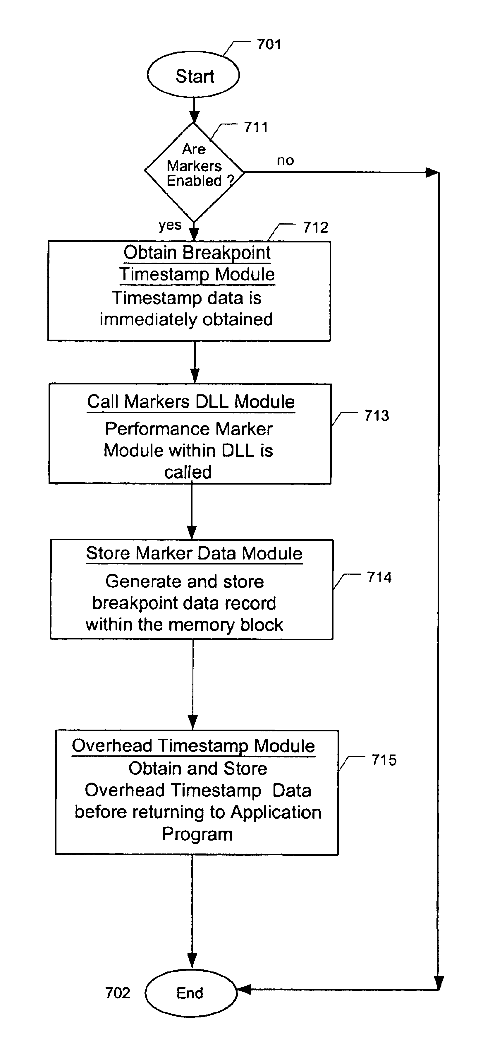
This is an application to a method, apparatus, and article of manufacture for inserting performance markers into programs to obtain and provide benchmark timing data regarding the run-time operation of the programs.

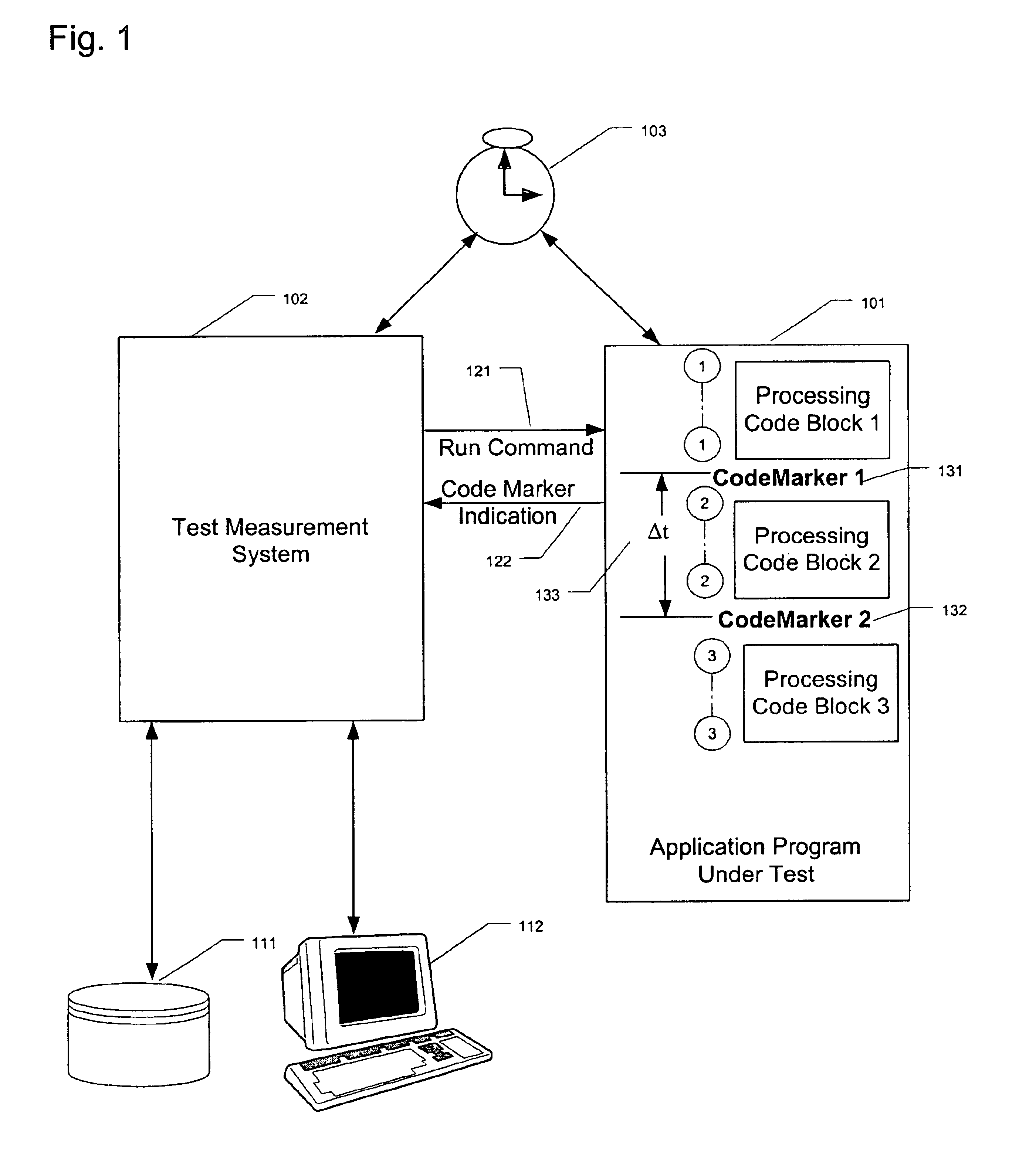
FIG. 1 illustrates an application program testing system according to one embodiment of the present invention. Typically, when an application program 101 is being tested, the application program 101 interacts with a test measurement system 102 in order to control the operation of the application program 101 during the test. The test measurement system 102 transmits a run command 121 to the application program being tested 101 to instruct the program 101 to begin its operations. A user typically has inserted one or more code markers within the application program 101 to indicate the points during the operation of the application program 101 in which runtime data is desired. When the operation of the application program 101 reaches a code marker, a code marker indication 12...


PUM


Abstract

A method, apparatus, and article of manufacture provide a mechanism for inserting performance markers into programs to obtain and provide data regarding the run-time benchmark timing of the programs. The computing system has an init module for determining if the benchmark timing data is to be collected during the operation of the application program, a performance marker module for obtaining and storing the benchmark timing data for later retrieval, and an uninit module for formatting and storing the obtained benchmark timing data into memory that permits retrieval after the termination of the application program. The init module is executed before any benchmark timing data is collected. The performance marker module is executed each time benchmark timing data is to be collected. The uninit module is executed after all benchmark timing data desired has been collected. The method and computer data product relate to a computer implemented process that inserts one or more code markers into the application program at locations within the application program corresponding to the point at which benchmark timing data is desired and that determines if benchmark timing data is to be collected at each code marker by checking for the existence of processing modules identified by an identification key within a system registry.

Description

TECHNICAL FIELDThis application relates in general to a method, apparatus, and article of manufacture for providing performance markers for testing of applications, and more particularly to a method, apparatus, and article of manufacture for inserting performance markers into programs to obtain and provide benchmark timing data regarding the run-time operation of the programs.BACKGROUND OF THE INVENTIONOne problem facing application program developers is how their application programs are to be tested. In order for the developers to test these programs, the developers need access to runtime state information regarding the internal operation of the program. This data can include memory usage, memory location contents, timing measurements for the execution of portions of the program, and similar data related to the state of the program while executing.In the past, application developers have needed to use third party tools to reinstrument the target application (an example of this bei...

Claims


Application Information

Patent Timeline
IPC IPC(8): G06F11/30G06F11/34
CPCG06F11/3419G06F11/3428G06F11/3466G06F2201/805G06F2201/865
Inventor RODRIGUES, JAMES P.ANNANGI, SUNEETHA
Owner MICROSOFT TECH LICENSING LLC
Why Eureka
Try Eureka