Supercharger with multiple backflow ports for noise control

Inactive Publication Date: 2005-04-05
GM GLOBAL TECH OPERATIONS LLC
View PDF16 Cites 35 Cited by
  • Summary
  • Abstract
  • Description
  • Claims
  • Application Information

AI Technical Summary

Benefits of technology

The present invention provides an improved supercharger using a plurality of graduated back flow ports to reduce supercharger noise, while maintaining supercharger efficiency. Valves regulate the amount and timing

Problems solved by technology

As the engine slows down, the leakage of back flow air from adv

Method used


Image

  • Supercharger with multiple backflow ports for noise control
  • Supercharger with multiple backflow ports for noise control
  • Supercharger with multiple backflow ports for noise control

Examples


Embodiment Construction

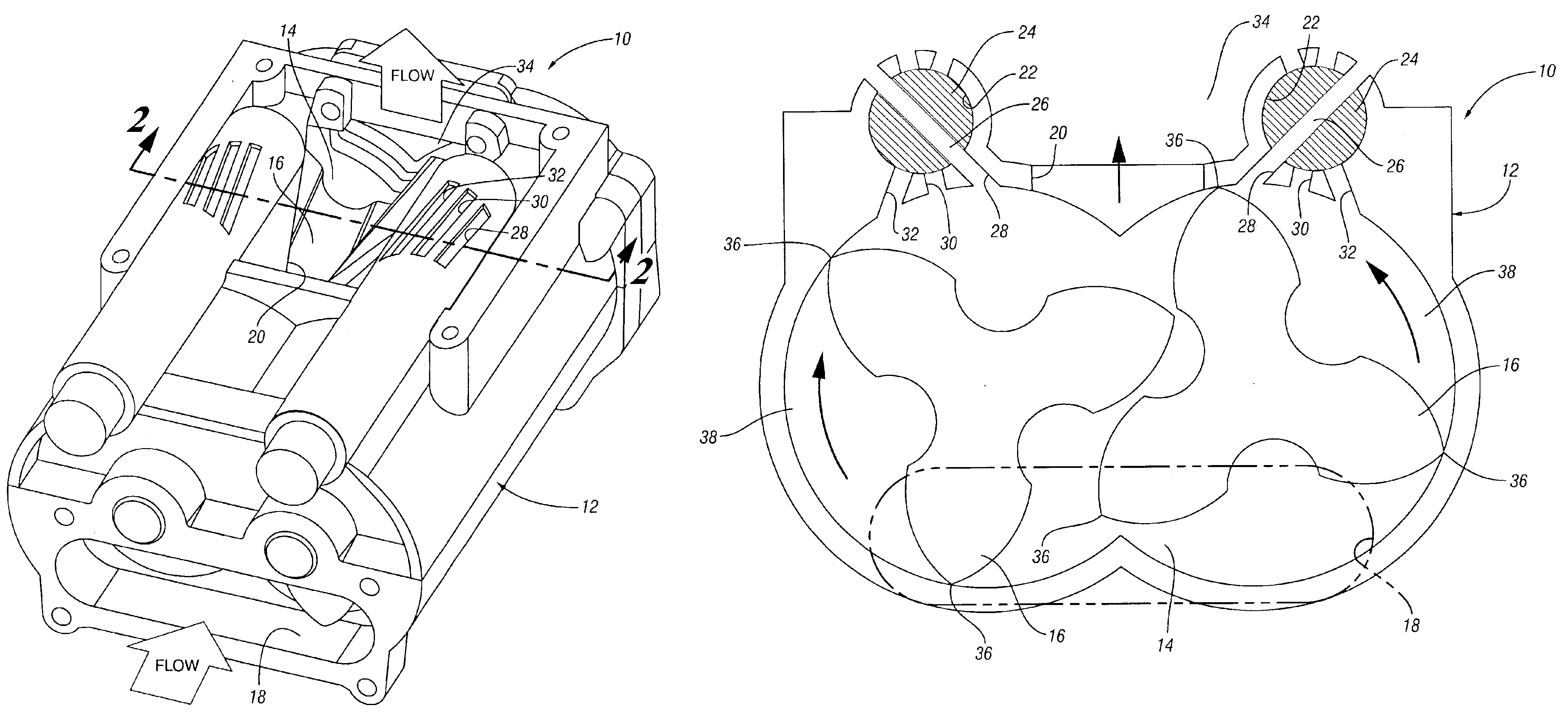
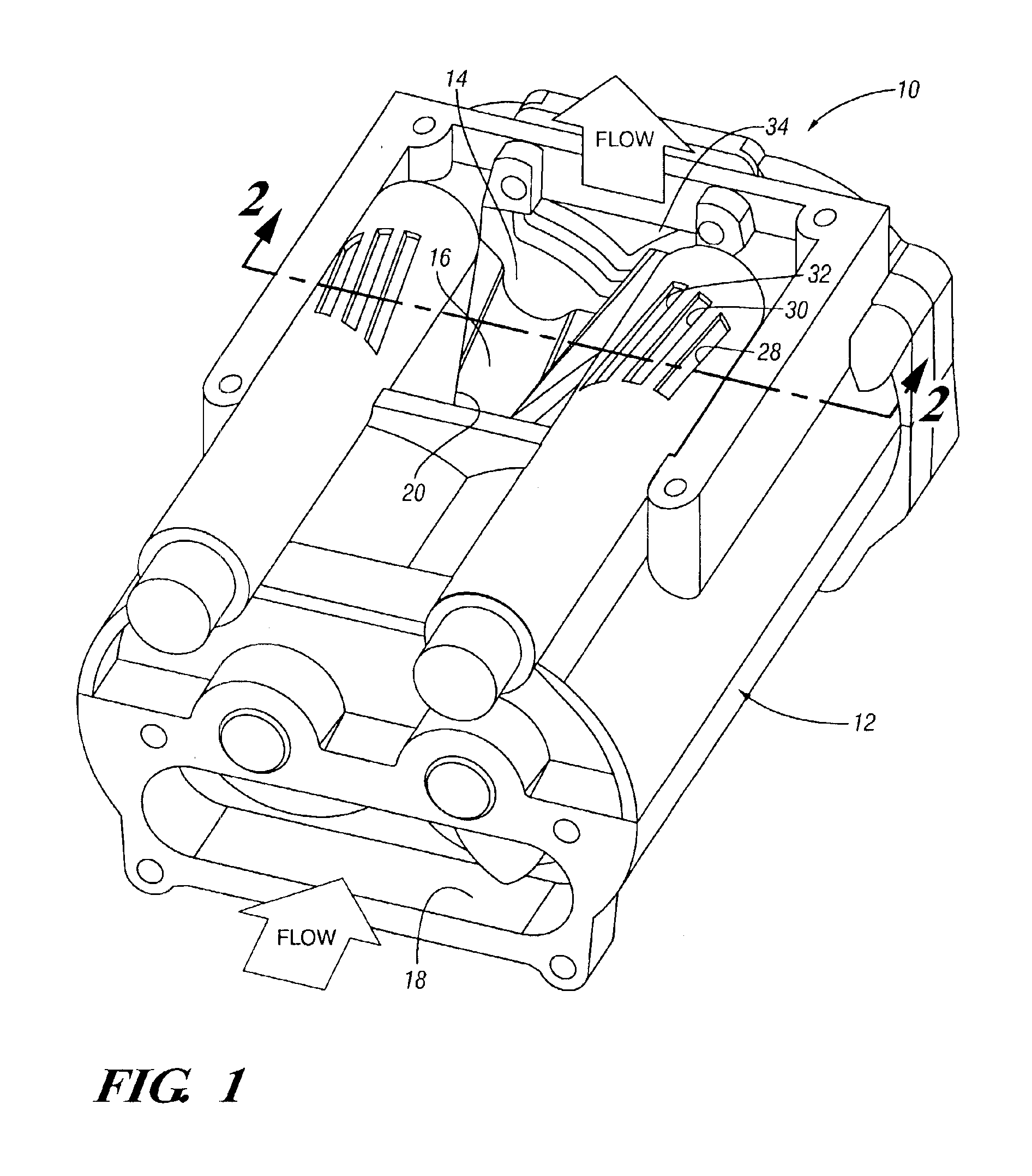
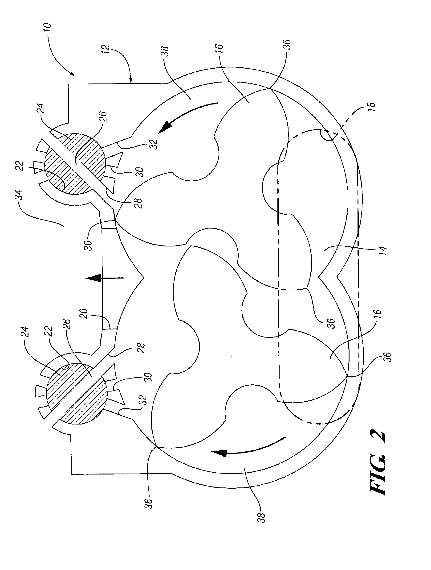
Referring to FIGS. 1-4 of the drawings in detail, numeral 10 generally indicates a roots-type engine supercharger having controllable back flow ports in accordance with the invention. Supercharger 10 includes a housing 12 having an internal cavity 14 in which a pair of three-lobed rotors 16 are rotatable in opposite directions as shown by the arrows in FIGS. 2-4. The lobes of the rotors preferably have a helical twist as they extend longitudinally in the housing in order to provide a relatively smooth discharge of air from the supercharger. However, such superchargers may also be made with other rotor configurations, such as straight rotors with two or more lobes.

Housing 12 includes an inlet opening 18 at one end of the housing, although such an opening could be provided on the lower side of the housing if desired for a particular application. A triangularly-shaped outlet opening 20 is provided toward the opposite end of the upper side of the housing, through which air drawn in thro...


PUM


Abstract

A supercharger includes multiple back flow ports which are controlled by valves. The valves regulate the timing and area for back flow of pressurized outlet air into the rotor chambers. The back flow air tends to equalize air pressure in the chambers prior to their exhausting into the outlet and thereby reduces flow back noise. The multiple ports are opened selectively or sequentially to provide noise control with improved efficiency at varying speeds.

Description

TECHNICAL FIELDThis invention relates to roots-type engine superchargers having backflow ports for reducing noise.BACKGROUND OF THE INVENTIONRoots-type superchargers are used to pump air into an engine at a rate greater than natural aspiration. The air enters the supercharger at nearly atmospheric pressure. Rotors in the supercharger carry nearly atmospheric air to an outlet port where the air is pressurized for delivery to the cylinders of an engine. The discharge of the nearly atmospheric air into the pressurized outlet creates back flow noise in the form of a pneumatic report or pop. When repeated at the high frequency which is typical of supercharger operation, this series of reports becomes a whine.Fixed back flow ports have been used to reduce noise by allowing a small amount of pressurized air to flow from the outlet of the supercharger into the nearly atmospheric rotor chambers. This tends to equalize the pressure between the outlet and the rotor chambers gradually so that w...

Claims


Application Information

Patent Timeline
IPC IPC(8): F01C11/00F04C29/00F04C29/06F02B33/00F02B33/38F01N1/00F04C18/16F04C28/14F04C28/24
CPCF01C11/008F02B33/38F04C28/14F04C28/24F04C29/0035F04C29/06F01N1/00F01N2260/14Y02T10/17F04C18/16Y02T10/12Y10T137/86751
Inventor PRIOR, GREGORY P.BITTNER, ROXANN M.
Owner GM GLOBAL TECH OPERATIONS LLC
Why Eureka
Try Eureka