Noise-optimized device for injecting fuel

a technology of optimizing device and fuel, which is applied in the direction of fuel injection apparatus, charge feed system, combustion engine, etc., can solve the problems of slow pressure reduction, and achieve the effect of avoiding cavitation phenomena and favorablely affecting noise developmen

Inactive Publication Date: 2005-04-05
ROBERT BOSCH GMBH
View PDF5 Cites 3 Cited by
  • Summary
  • Abstract
  • Description
  • Claims
  • Application Information

AI Technical Summary

Benefits of technology

If the pressure always remains above the vapor pressure during the refilling of the hollow spring holder chamber, cavitation phenomena can be avoided, which favorably affects the noise developed in this kind of unit injector system.

Problems solved by technology

Leaks for production and tolerance reasons at the storage piston guide causes slow reduction in the pressure, until it drops below the closing pressure of the reservoir, and the storage piston closes slowly.

Method used


Image

  • Noise-optimized device for injecting fuel
  • Noise-optimized device for injecting fuel
  • Noise-optimized device for injecting fuel

Examples


Embodiment Construction

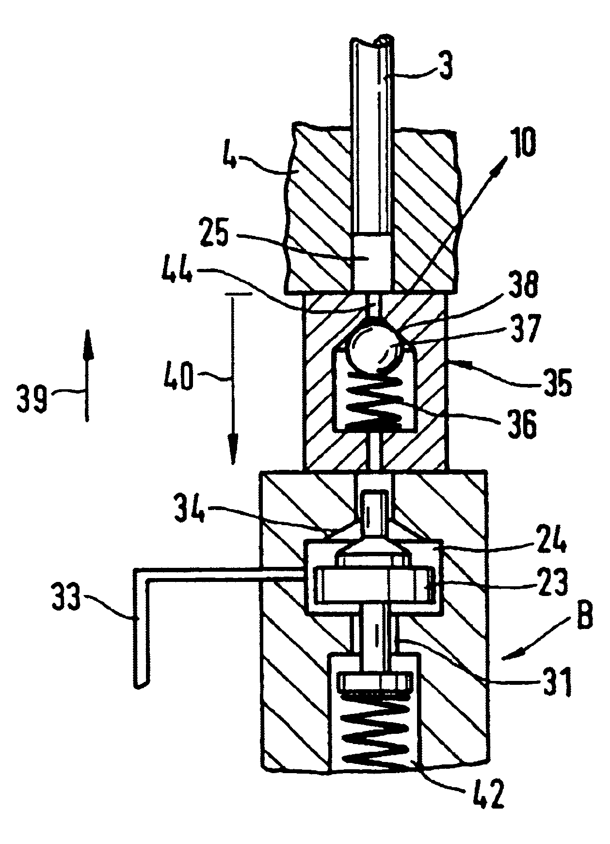
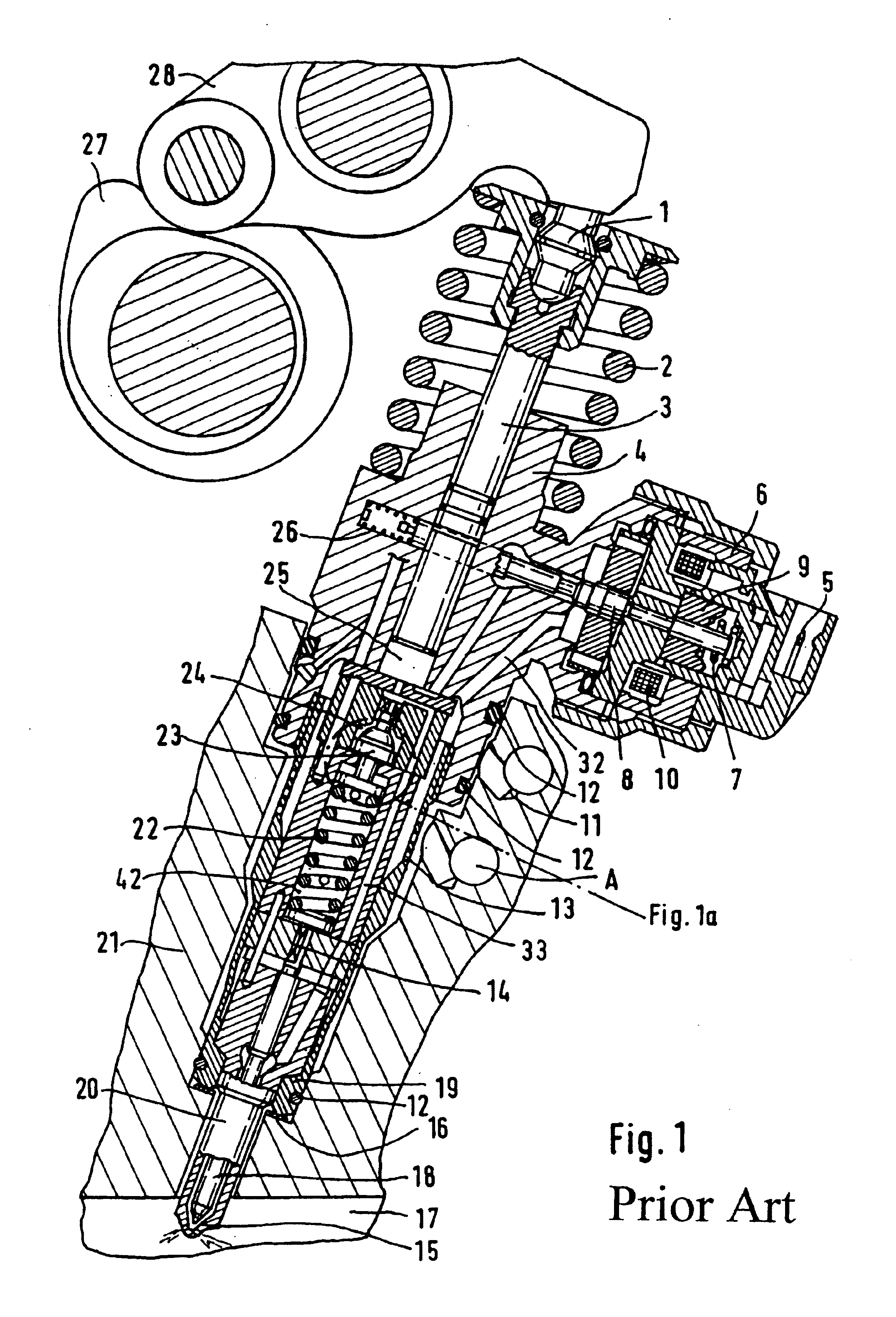
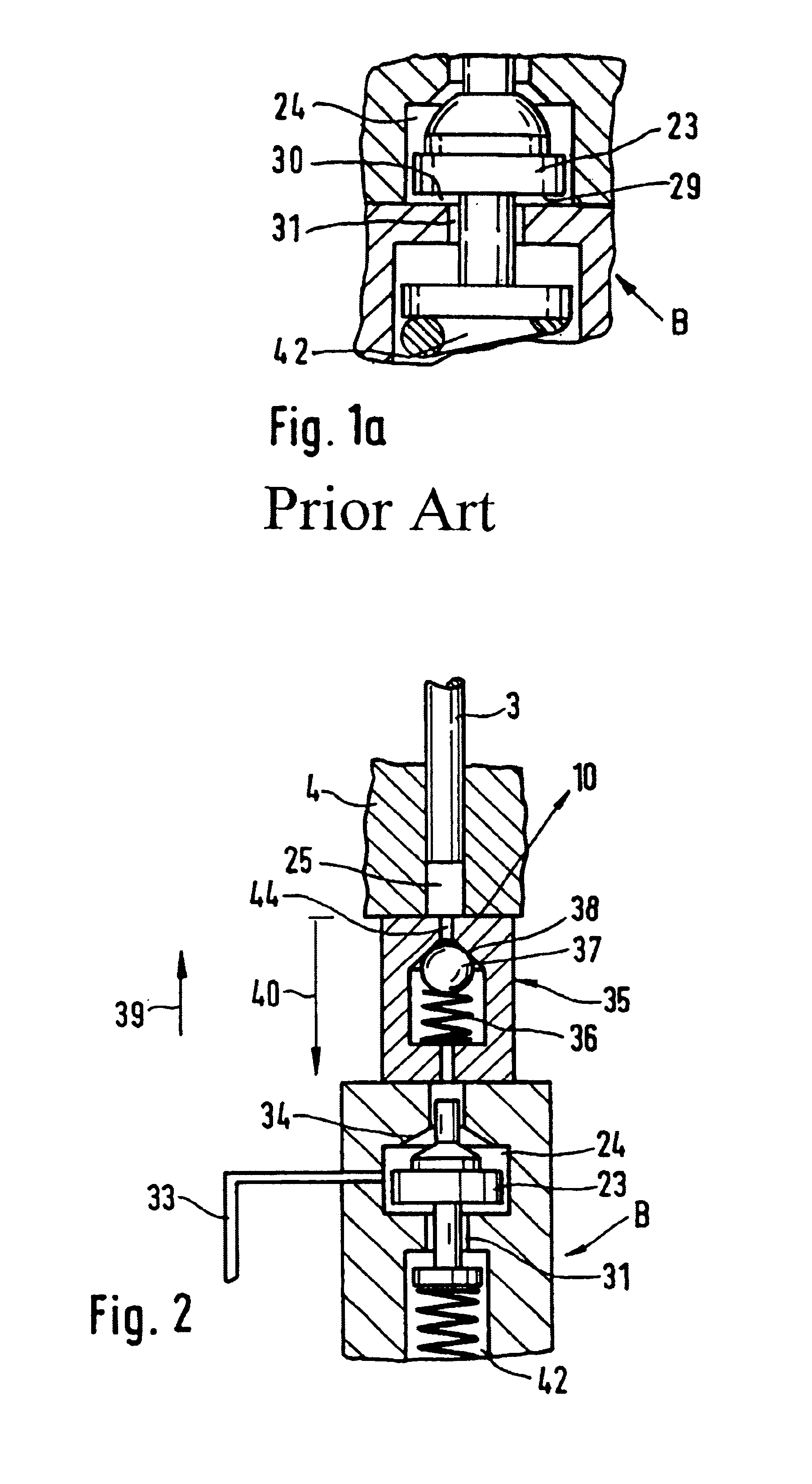
In the unit injector system shown in FIG. 1, a pump piston 3, which is received movably in a pump body 4, is actuated via a spherical bolt 1. The spherical bolt 1 in turn is actuated via a tiltably disposed tilt lever 28, which is provided on one of its ends with a rotatably supported roller body. The roller body rolls along a cam of a driving camshaft 27. The deflection of the tilt lever 28 about its pivot axis depends on the course of the shaping of the top of the cam, which in the view of FIG. 1 extends eccentrically to the pivot axis of the driving camshaft 27.

The pump piston 3 of the pump body 4 of the unit injector system is acted upon by a restoring spring 2, which is braced on one end on a plane face of the pump body 4 and on the other on a caplike support element, which is disposed in the upper region of the pump piston 3 that is movable in the pump body 4.

Laterally of the pump body 4 is an actuator, which in the exemplary embodiment shown in FIG. 1 includes a magnet coil 1...


PUM


Abstract

The invention relates to a unit injector system for supplying the combustion chamber of a self-igniting internal combustion engine with fuel. The unit injector system has a high-pressure chamber that can be subjected to pressure via a pump piston. A storage piston is received inside a storage chamber and is acted upon via a compression spring disposed in a spring holder. A return flow throttle element, which delays the buildup of pressure in the storage chamber, is disposed between the high pressure chamber and the storage chamber of the storage piston.

Description

BACKGROUND OF THE INVENTION1. Field of the InventionIn systems for injecting fuel into the combustion chamber of internal combustion engines, component parts such as switching valves and injection nozzles in high-pressure pumps and in the various embodiments of injectors, nozzle holder combinations, or unit injector systems are made to move. Their motion positively displaces a volume which is replenished on the intake side. For the requisite volumetric flow, the pressures and cross sections must be adapted. If the replenishment of fuel is inadequate, the pressure on the intake side drops. If the vapor pressure of the fluid to be pumped fails to be attained, the column of liquid breaks off, causing cavitation bubbles to form. Upon recompression of the fuel to above the vapor pressure, the collapse of the vapor bubbles causes noise.2. Description of the Prior ArtWith present unit injector systems in self-igniting internal combustion engines, mechanically-hydraulically controlled prein...

Claims


Application Information

Patent Timeline
Patent Type & Authority Patents(United States)
IPC IPC(8): F02M61/20F02M59/00F02M59/46F02M61/00F02M55/04F02M55/00F02M45/08F02M45/00F02M57/00F02M57/02F02M59/36F02M59/20F02M61/14F02M63/00F02M53/00
CPCF02M45/08F02M55/04F02M59/466F02M61/205F02M53/00F02M55/007F02M57/023F02M2200/304F02M61/14F02M2200/04F02M59/366
Inventor PARCHE, MARCUS
Owner ROBERT BOSCH GMBH
Why Eureka
Try Eureka