Compressor having independently driven members

a compressor and independent technology, applied in the direction of positive displacement liquid engines, piston pumps, liquid fuel engines, etc., can solve the problems of large compressor body size and inability to work in the refrigeration cycle system, and achieve the effect of simple and inexpensive motor construction, easy variation and convenient us

Inactive Publication Date: 2005-04-05
DENSO CORP
View PDF10 Cites 12 Cited by
  • Summary
  • Abstract
  • Description
  • Claims
  • Application Information

AI Technical Summary

Benefits of technology

An object of the present invention is to provide a hybrid compressor device whose body is compact.
Another aspect of the present invention is to provide the hybrid compressor apparatus that is effectively operated according to various vehicle traveling conditions.
If the driven member drives the first compression member and the control device controls the motor in such a manner that the motor separately drives the second compression member in a rotating direction opposite to that of the first compression member in a normal vehicle traveling, the rotation speed of the first compression member relative to the second compression member increases so that a discharge amount of the compressor increases, compared to that of a conventional hybrid compressor apparatus in which the second compression member is always in state of rest. Accordingly, the compressor of the hybrid compressor apparatus can have a larger discharge capacity with a more compact structure.
On the other hand, if the driven member drives the first compression member and the second compression member is rotated along with the first compression member in the same rotating direction as that of the first compression member and, in this state, rotation amount of the second compression member along with the first compression member is adjusted by the control device that controls induced current to be generated in the motor, the rotation speed of the first compression member relative to the second compression member increases so that the discharge amount of the compressor increases. Accordingly, the discharge capacity of the compressor can be easily changed according to vehicle traveling conditions without using a variable capacity mechanism.
It is preferable that the compressor is of a fixed capacity type in which a discharge capacity per rotation of the first compression member relative to the second compression member is fixed to a given value. Accordingly, the compressor itself is inexpensive. Even if the compressor is of the fixed capacity type and not provided with a variable capacity mechanism, the discharge capacity of the compressor can be easily varied by controlling the operations of the motor and the electromagnetic clutch.
Moreover, preferably, the motor has a rotor and a stator on which a coil is wound. Power of the external electric source is applied directly to the coil without a power transmission interface such as a slip ring so that a construction of the motor is simple and inexpensive.

Problems solved by technology

Accordingly, the refrigeration cycle system does not work as a cooler during a period when the engine stops.
However, in the hybrid compressor apparatus mentioned above, the motor for driving the compressor is used only when the engine stops and is not used as a drive unit during any vehicle traveling conditions.
In a case that the compressor is driven only by the engine whose operation depends on the vehicle traveling conditions, the larger capacity of the compressor results in a larger body size of the compressor.

Method used


Image

  • Compressor having independently driven members
  • Compressor having independently driven members
  • Compressor having independently driven members

Examples


first embodiment

(First Embodiment)

A first embodiment is described with reference to FIGS. 1 to 4.

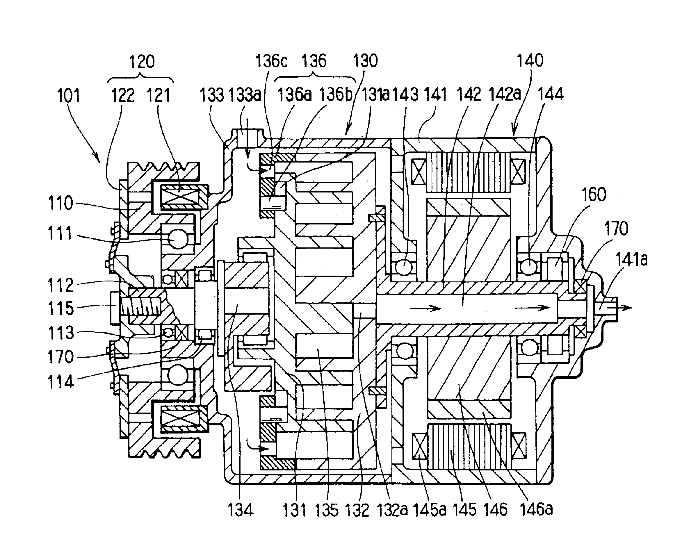
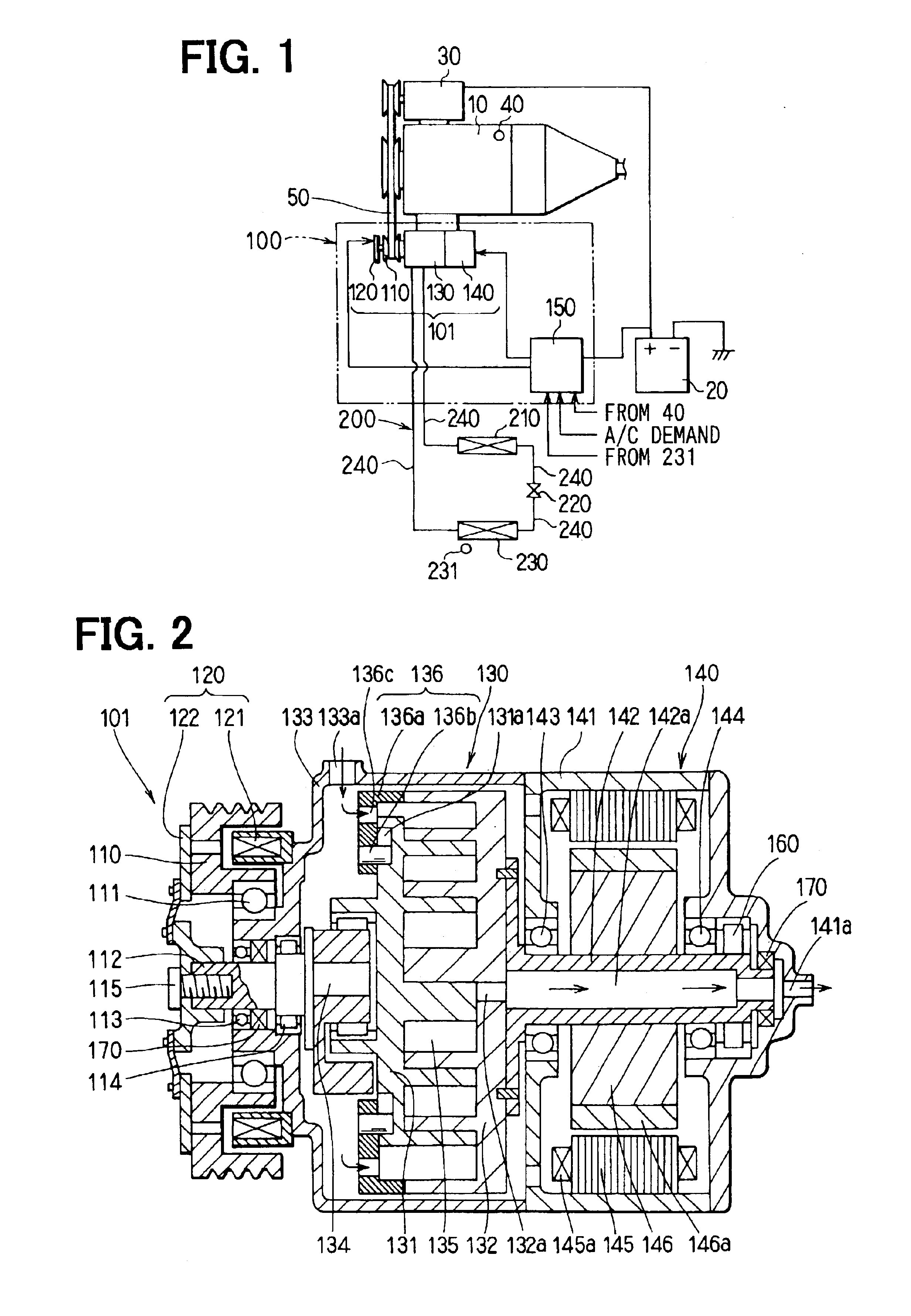
As shown in FIG. 1, A hybrid compressor apparatus 100 is applied to a refrigeration cycle system 200 installed in a vehicle having an idle stop mechanism in which an engine (external driving source) 10 stops with temporary stop of the vehicle during its traveling. The hybrid compressor apparatus 100 is composed of a hybrid compressor 101 and a control device 150 for controlling the hybrid compressor 101. A motor generator 30, which generates current upon receipt of driving force from the engine 10 and charges a battery 20 as an external electric source, and a revolution sensor 40 for detecting revolution number of the engine 10 are mounted on the engine 10.

The refrigeration cycle system 200, which constitutes a known refrigeration cycle, is composed of the hybrid compressor apparatus 100 including the hybrid compressor 101 that has a compressor 130 for compressing coolant within the refrigeration cycle ...

second embodiment

(Second Embodiment)

A hybrid compressor according to a second embodiment is described with reference to FIGS. 8 and 9.

According to the second embodiment, the electromagnetic clutch 120 is not provided between the pulley 110 and the first movable scroll 131 and the pulley 110 is directly connected to the hub 120. Further, the one-way clutch 160 is not provided on an axial end side of the rotating motor shaft 142.

Accordingly, induced current is generated in a motor 140 since the second movable scroll 132 is rotated along with the first movable scroll 131 that is driven by the pulley 110. The control device 150 controls the rotation amount of the second movable scroll 132 rotatable along with the first movable scroll 131.

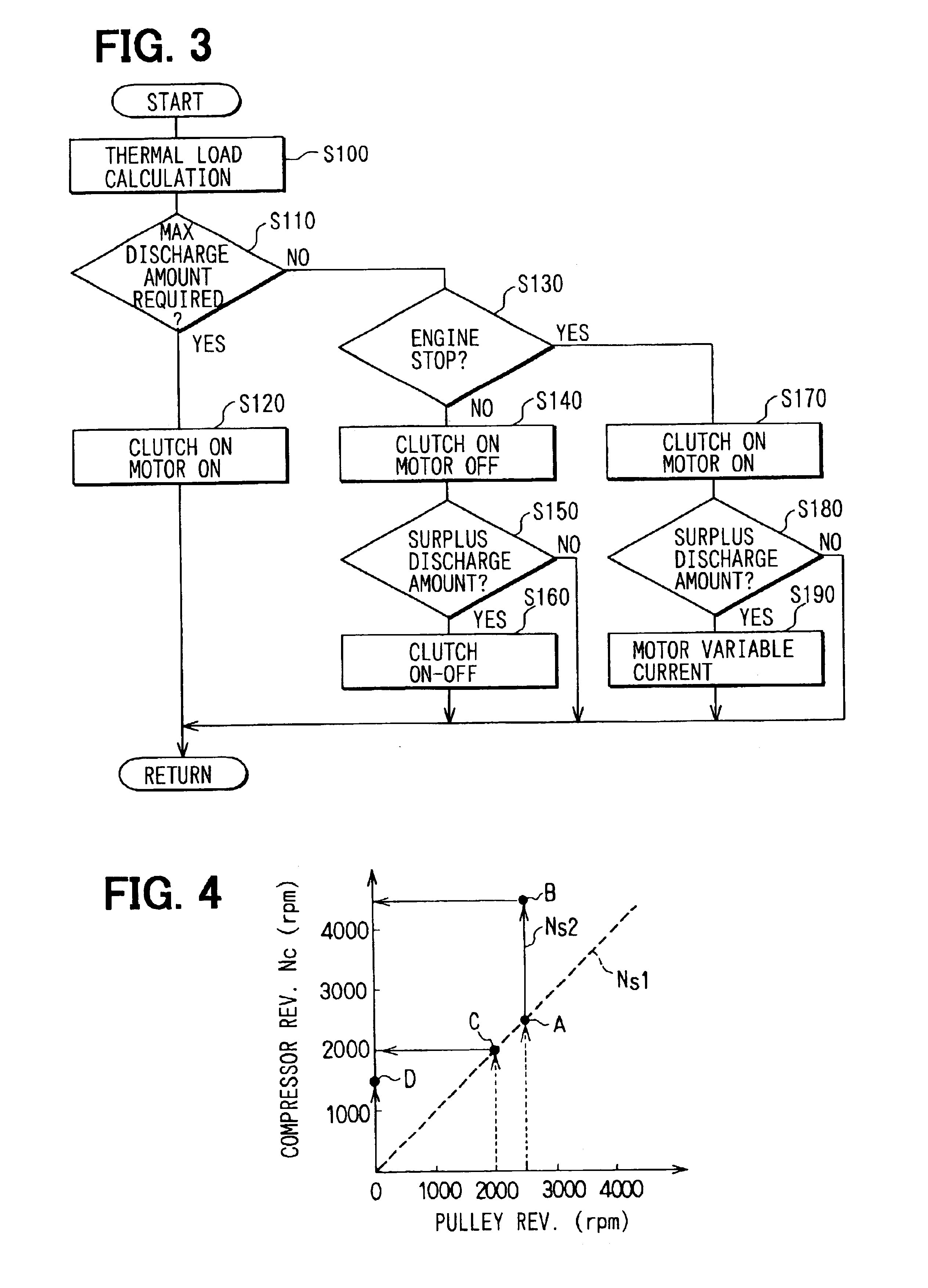
The second movable scroll 132 rotates in the same direction as the first movable scroll 131 so that the revolution number Nc of the compressor, which is the revolution number Ns1 (presumably, 2500 rpm) of the first movable scroll 131 relative to the revolution number Ns...


PUM


Abstract

The hybrid compressor apparatus is composed of a compressor in which fluid is compressed by varying a volumetric capacity of a compression space provided between a first compression member and a second compression member, which are movable independently of each other, according to rotation of the first compression member relative to the second compression member, a motor rotatable upon receipt of power of an external electric source, and a driven member rotatably driven by motive force transmitted from an external driving source. The first compression member is connected with the driven member and the second compressor is connected with the motor. If maximum discharge amount is required for the compressor, the motor is driven separately by a control device when the driven member drives the first compression member so that the second compression member is rotated in a direction opposite to that of the first compression member.

Description

BACKGROUND OF THE INVENTION1. Field of the InventionThe present invention relates to a hybrid compressor apparatus, preferably, applicable to a refrigeration cycle system installed in a vehicle having an idle stop mechanism in which an engine stops with temporary stop of the vehicle during its traveling.2. Description of the Prior ArtRecently, a vehicle incorporating an idle stop mechanism has been put on a market in view of saving fuel consumption. In this vehicle, a compressor for a refrigeration cycle system, driven by an engine, is obliged to stop, when the engine stops with temporary stop of the vehicle during its traveling. Accordingly, the refrigeration cycle system does not work as a cooler during a period when the engine stops.U.S. Pat. No. 6,375,436 discloses a hybrid compressor apparatus in which the above problem is solved. According to this hybrid compressor apparatus, a pulley to which rotating force of the engine is communicated is linked via an electromagnetic clutch...

Claims


Application Information

Patent Timeline
Patent Type & Authority Patents(United States)
IPC IPC(8): F04C18/02F04C18/34F04C25/00F04C29/00F04C18/344F04C23/02F04B35/00F04B49/06F04C28/00
CPCF04C18/023F04C18/3442F04C29/0085F04C25/00F04C2240/45
Inventor IWANAMI, SHIGEKI
Owner DENSO CORP
Why Eureka
Try Eureka