High density patching system

a patching system and high density technology, applied in the field of patching systems, can solve the problems of not allowing users to configure the circuits connected to individual devices, users of these types of devices and jack fields have very complex and dense wiring environments within their physical plants, and achieve the effect of high density patching system and enhanced circuit density of the system

Inactive Publication Date: 2005-04-05
COMMSCOPE TECH LLC
View PDF23 Cites 12 Cited by
  • Summary
  • Abstract
  • Description
  • Claims
  • Application Information

AI Technical Summary

Benefits of technology

One inventive aspect of the present disclosure relates to a high density patching system. The patching system includes a plurality of jacks patching circuitry for providing patching functions. The jacks also include integral switching devices for changing the circuit configurations of the patching circuitry. For example, in one embodiment, the switching devices are adapted for changing the patching circuitry between a normal-out configuration, a half-normal configuration, a normal-strapped configuration and a sleeve-normal configuration. In one embodiment, the circuit density of the system is enhanced by positioning the switching devices directly behind the patching circuitry.

Problems solved by technology

This type of design does not allow the users to configure the circuits connected to individual devices and required all devices connected to a particular jack field to be configured identically.
In addition, users of these types of devices and jack fields have very complex and dense wiring environments within their physical plants.

Method used


Image

  • High density patching system
  • High density patching system
  • High density patching system

Examples


Embodiment Construction

In the following detailed description, references are made to the accompanying drawings that depict various embodiments in which the inventive aspects may be practiced. It is to be understood that other embodiments may be utilized, and structural and functional changes may be made without departing from the scope of the inventive aspects.

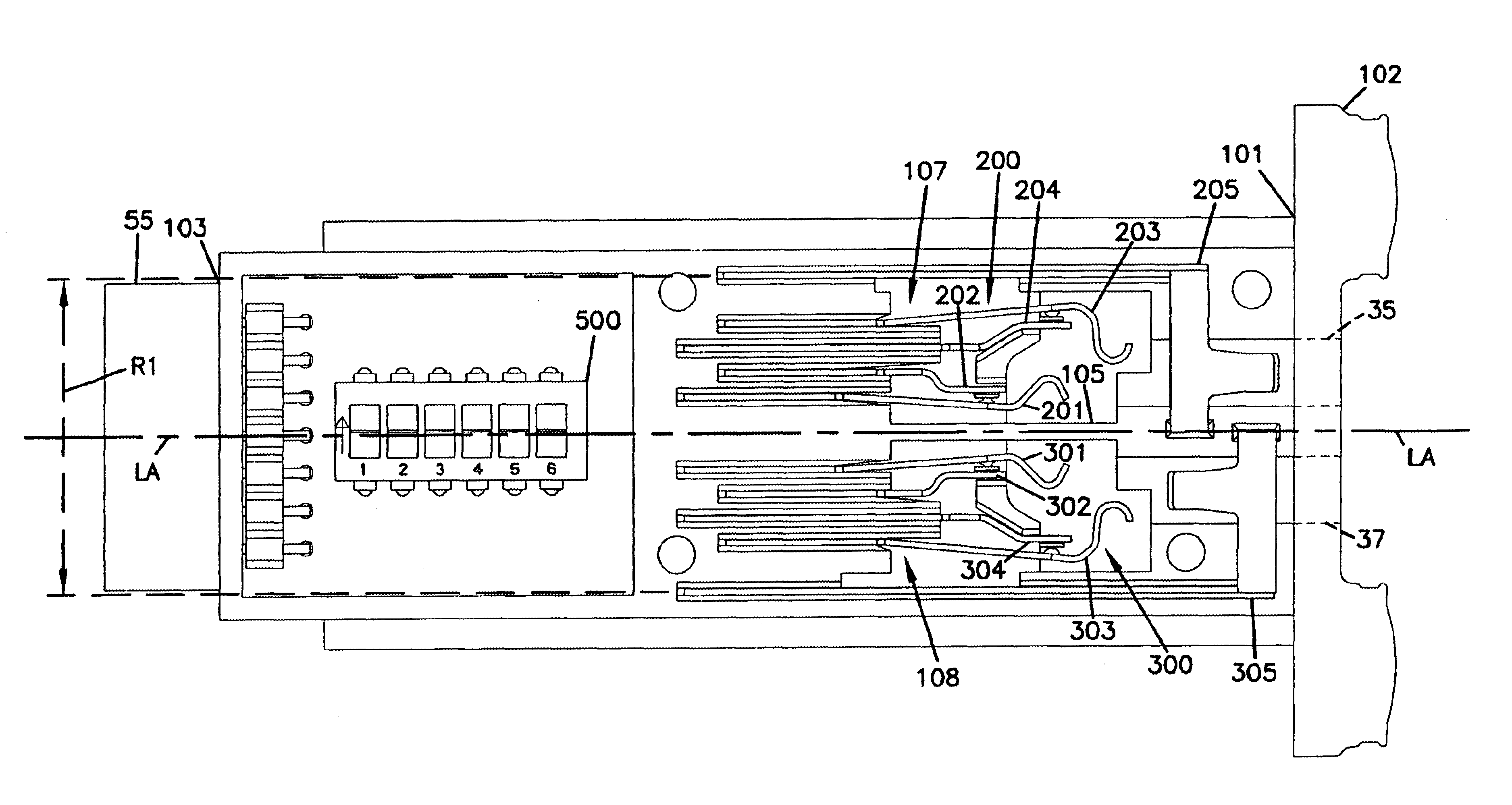
FIG. 4 illustrates a patching system 20 having features that are examples of inventive aspects in accordance with the principles of the present disclosure. The patching system 20 includes a chassis 22 having a front side 24 and a rear side 26. The patching system 20 also includes jacks 28 that insert into the chassis 22 through the front side 24 of the chassis 22, and a rear connector assembly 36 accessible from the rear side 26 of the chassis 22. The jacks 28 provide patch plug access (e.g., via upper and lower ports 35, 37), and the rear connector assembly 36 includes connectors 38a, 38b adapted for connection to equipment such as audio and data s...


PUM


Abstract

A patching system is disclosed herein. The patching system includes a plurality of patching jacks. The jacks include switches for changing the circuit configurations of the patching circuitry of the jacks. The switches are positioned to enhance the circuit density of the patching system.

Description

FIELD OF THE INVENTIONThe present invention relates to patching systems for audio and video applications.BACKGROUNDAnalog and digital audio signals are transmitted over balanced and shielded twisted pair cables. These cables include a pair of insulated conductors, either stranded or solid wire, which are surrounded by a metal foil shield. The shield serves to reduce the impact of external electromagnetic inference on the signal being transmitted over the cable and also to reduce the electromagnetic field generated by the signals being transmitted over the cable.In a professional audio and video industry application, a large number of such cables will be in use to carry signals from sources to processing devices such as mixers or equalizers and further to amplifiers or other downstream devices. The environment in which these signals are generated is quite dynamic and requires the ability to quickly and easily shift connections between sources, and downstream devices. A jack field pro...

Claims


Application Information

Patent Timeline
Patent Type & Authority Patents(United States)
IPC IPC(8): H01R13/703H01R13/70H04Q1/02H04Q1/14H01R24/58
CPCH01R13/7033H04Q1/13H04Q1/116H01R2201/18
Inventor MUSOLF, BRUCEPAUTZKE, ROGERPETERS, JEFFGOOD, THOMAS
Owner COMMSCOPE TECH LLC
Why Eureka
Try Eureka