
Bone access system

a bone access and bone technology, applied in the field of bone access systems, can solve the problems of less than optimal actuation and control of the system, affecting the accuracy of bone access, so as to reduce user risk and ease of use, the effect of low stiffness and easy setting

Inactive Publication Date: 2005-04-05
NEUROTHERM
View PDF10 Cites 307 Cited by
  • Summary
  • Abstract
  • Description
  • Claims
  • Application Information

AI Technical Summary

Benefits of technology

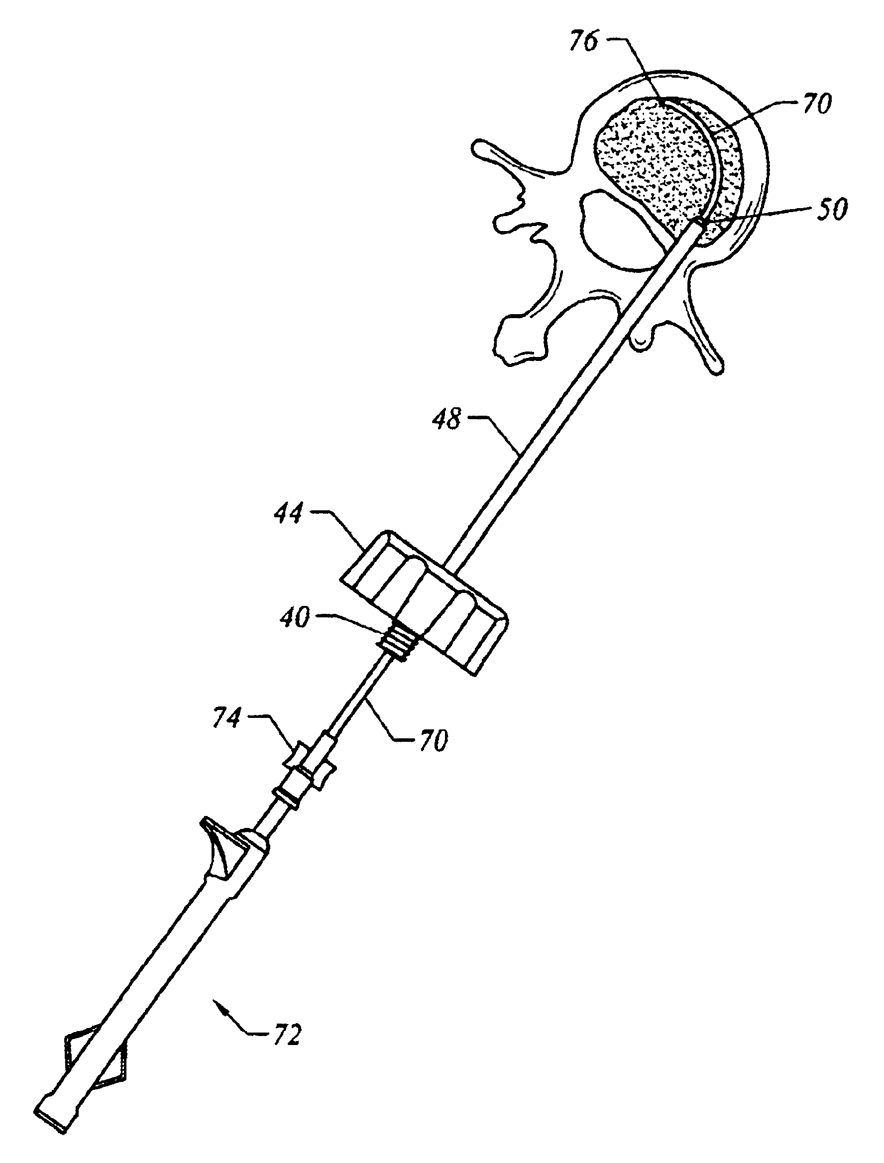
The present invention is a bone access system offering radial access to sites with reduced user risk and ease of use. The inventive system employs a flexible (semi-rigid) conduit that is formed into a curved shape by a curved core wire once the end of each item is advanced beyond the end of a cannula which restrains the core member (via the intermediately-located conduit). The core wire has a relatively low stiffness so it is easily set within the cannula (either together with the conduit or after the conduit has been placed therein). Various types of material may be employed for the curved core wire or guide wire including titanium, nickel-titanium, steel alloys or plastic / composite members.
Additionally, the present invention is suited for use with an actuation sheath between the core member and conduit that is capable of independently straightening the preformed section of the wire. This allows for articulation of the curve independent of its relation to the end of the cannula. Yet another aspect of the invention provides an active tip (e.g., a drill bit or chisel) at the end of the core member. Such an active tip may be actuated by twisting, oscillating or other motion relative to the conduit to assist in advancing the co-axial conduit through bony matter. Still further, the invention may employ a serrated conduit end, possibly provided by a metal crown to assist in obtaining a bone biopsy sample.

Problems solved by technology

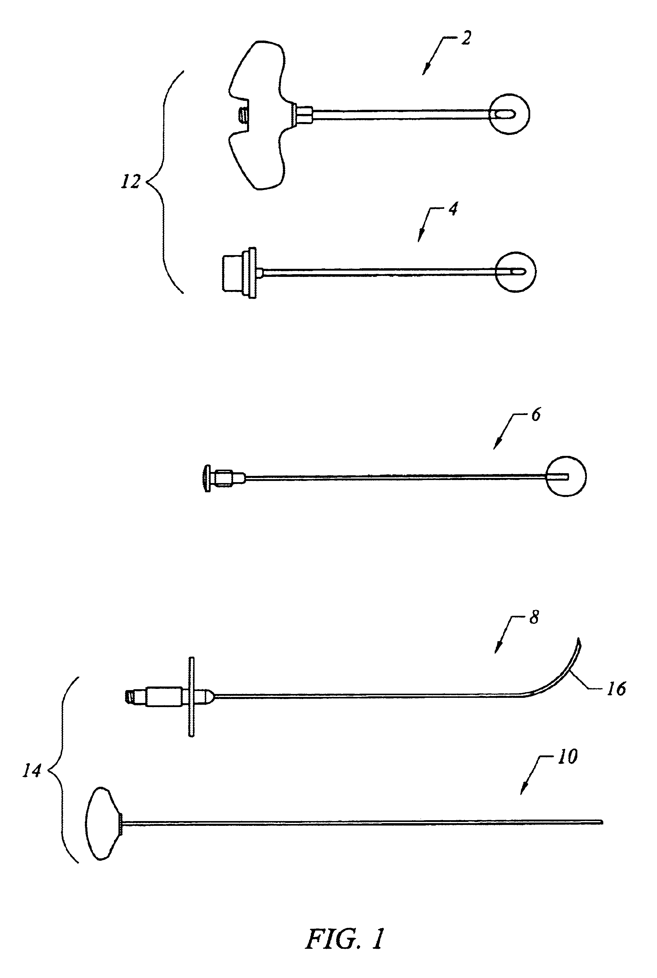
Especially when withdrawing the curved needle from the cannula (but also in loading it into the cannula), the system presents high risk to users.
In addition to the user safety issues the device presents, the difficulty presented in straightening needle 8 within cannula 4 produces significant frictional forces between the members resulting in less than optimal actuation and control of the system.
Furthermore, the insertion or removal (at least partial removal) activity of the curved needle into and out of the cannula occurs when cannula 2 is set within a patient's body makes any such manipulation more difficult.

Method used


Image

  • Bone access system
  • Bone access system
  • Bone access system

Examples


Embodiment Construction

Before the present invention is described in detail, it is to be understood that this invention is not limited to particular variations set forth and may, of course, vary. Various changes may be made to the invention described and equivalents may be substituted without departing from the true spirit and scope of the invention. In addition, many modifications may be made to adapt a particular situation, material, composition of matter, process, process act(s) or step(s), to the objective(s), spirit or scope of the present invention. All such modifications are intended to be within the scope of the claims made herein.

Methods recited herein may be carried out in any order of the recited events which is logically possible, as well as the recited order of events. Furthermore, where a range of values is provided, it is understood that every intervening value, between the upper and lower limit of that range and any other stated or intervening value in that stated range is encompassed withi...


PUM


Abstract

Instruments and methodology for nonlinear access to bone tissue sites are described. Embodiments disclosed include a conduit for delivering material or a medical device to a site and a core member that is able to steer the conduit and allow the combination to be advanced thorough cancellous bone. A cannula and stylet may be provided to first advance through hard bone. The core member includes a curved tip that may be straightened by the cannula or an actuator sheath to vary sweep of the curve. An obturator may be included in the system. This instrument may include a flexible portion as well. Each of the obturator and conduit may be provided with any of a variety of active tips. The systems may be used to perform hard tissue site implantation, for example, in connection with a high pressure injection system.

Description

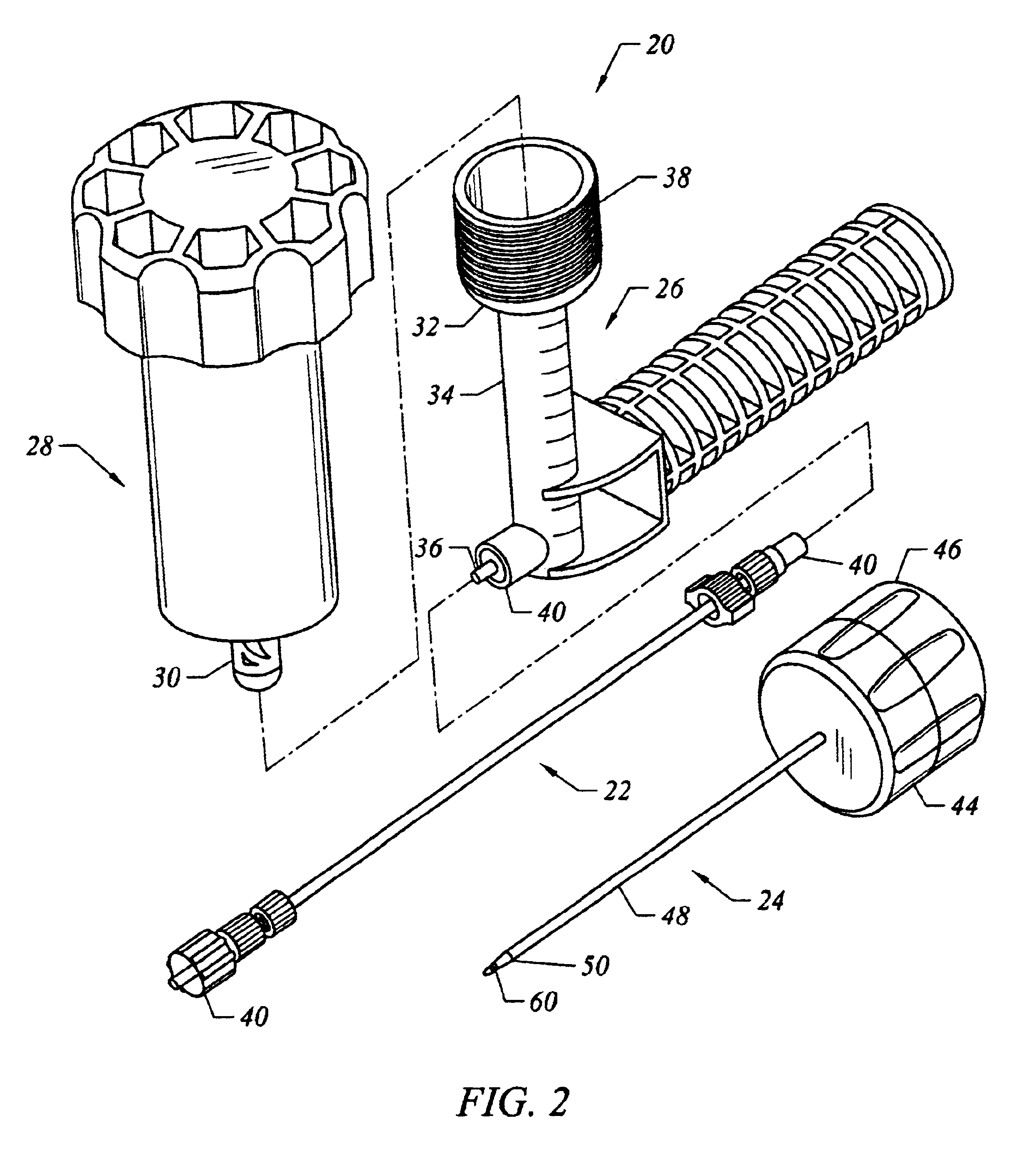
FIELD OF THE INVENTIONThis invention relates to apparatus for accessing bone for conveying fluids, solids or medical devices thereto. More particularly, it involves a system for access to bone or other hard tissue, where the system has a manipulable or steerable end to reach radially disposed sites.BRIEF DESCRIPTION OF THE DRAWINGSFIG. 1 represents information known in the art and is referenced in the Background of the Invention. FIGS. 2-16B diagrammatically illustrate aspects of the present invention. Variation of the invention from that shown in the figures is contemplated.FIG. 1 is a plan view of various bone access tools sold by Cook Medical, Inc.FIG. 2 is a perspective view of a high pressure injection system that may be used in connection with the present invention.FIGS. 3A-3C are perspective views of a cannula and stylets that may be used with the high pressure injection system.FIGS. 4A-4C″ are perspective views in which FIGS. 4A and 4B show access and implant material delive...

Claims


Application Information

Patent Timeline
IPC IPC(8): A61B17/88A61B17/34A61B17/32A61B17/00A61B10/00A61B10/02A61B10/06
CPCA61B17/3417A61B17/3468A61B17/3472A61B17/8819A61B17/8811A61B10/025A61B10/06A61B2017/320032A61B17/8875A61B2017/00261A61B2017/003A61B2017/00867
Inventor ARRAMON, YVES P.MCINTYRE, SCOTT H.
Owner NEUROTHERM
Learn More