Electomagnetic detection apparatus

a detection apparatus and electromagnetic technology, applied in the field of electromagnetic detection apparatus, can solve the problems of noise becoming a problem, pbs detectors having a number of limitations, and the type of noise known as 1/f noise predominate, so as to reduce the variation of detector signals

Inactive Publication Date: 2005-04-05
NDC INFRARED ENG
View PDF8 Cites 6 Cited by
  • Summary
  • Abstract
  • Description
  • Claims
  • Application Information

AI Technical Summary

Benefits of technology

In an infrared measuring gauge, improvement of the linearity tends to enhance the temperature stability of the measuring gauge and lead to more predictable calibration. Extension of the detector frequency response permits the use of much faster filter data rates, and thus reduces the response time of the measuring gauge. Faster filter speeds also result in reduced ambient light sensitivity and can lead to improvements in noise.
In another embodiment of the invention, the controlling means are arranged to adjust the intensity of the radiation emitted by the radiation source in order to minimise variations in the detector signal.

Problems solved by technology

However, PbS detectors have a number of limitations, including particularly the following:(a) Temperature sensitivity: the resistance of a typical detector cell falls by 25% for every 10° C. rise in temperature.(b) Non-linearity: the response of the detector to incident radiation is not linear over the whole operational range of the detector.(c) Response time: the response time of the detector usually limits the rate at which different wavelengths can be detected, that is the rate at which successive filters can be employed.
Faster filter data rates tend to result in the signal from the wavelength obtained from one filter lagging so much that it bleeds into that from the wavelength obtained from the next filter, thereby causing “cross-talk”.(d) Noise: at low frequencies of operation of the detector a type of noise known as 1 / f noise predominates.
If a relatively low filter data rate is chosen to avoid cross-talk, then such noise becomes a problem.
It is apparent from the, above that the detectors currently used in measuring gauges suffer from a number of drawbacks, not the least of which is their response time.

Method used


Image

  • Electomagnetic detection apparatus
  • Electomagnetic detection apparatus
  • Electomagnetic detection apparatus

Examples


Embodiment Construction

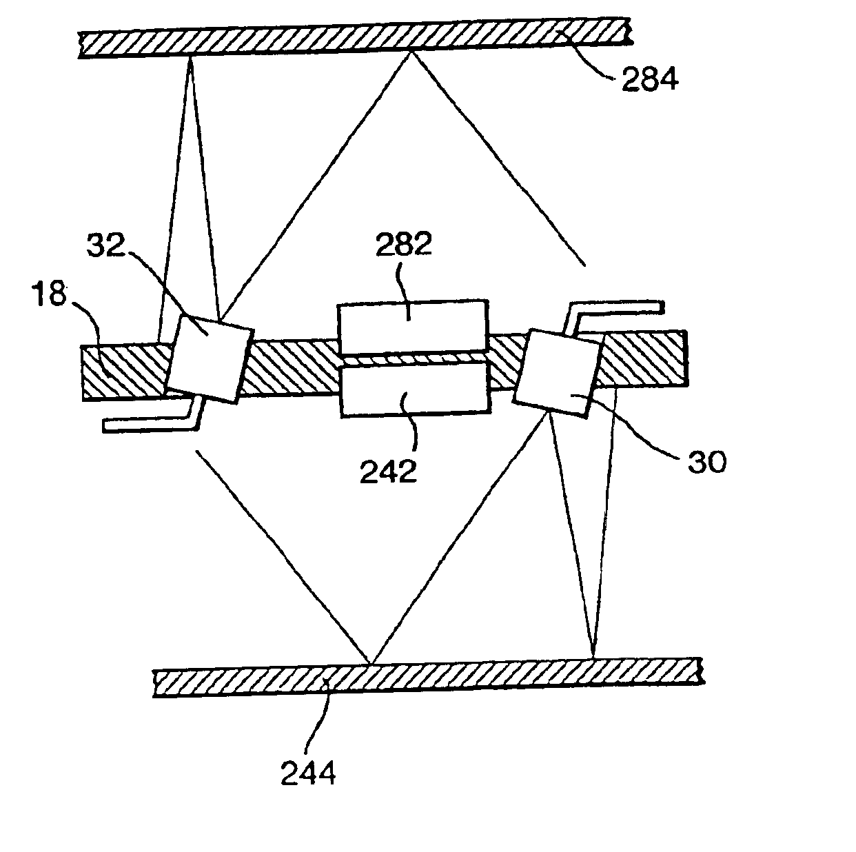
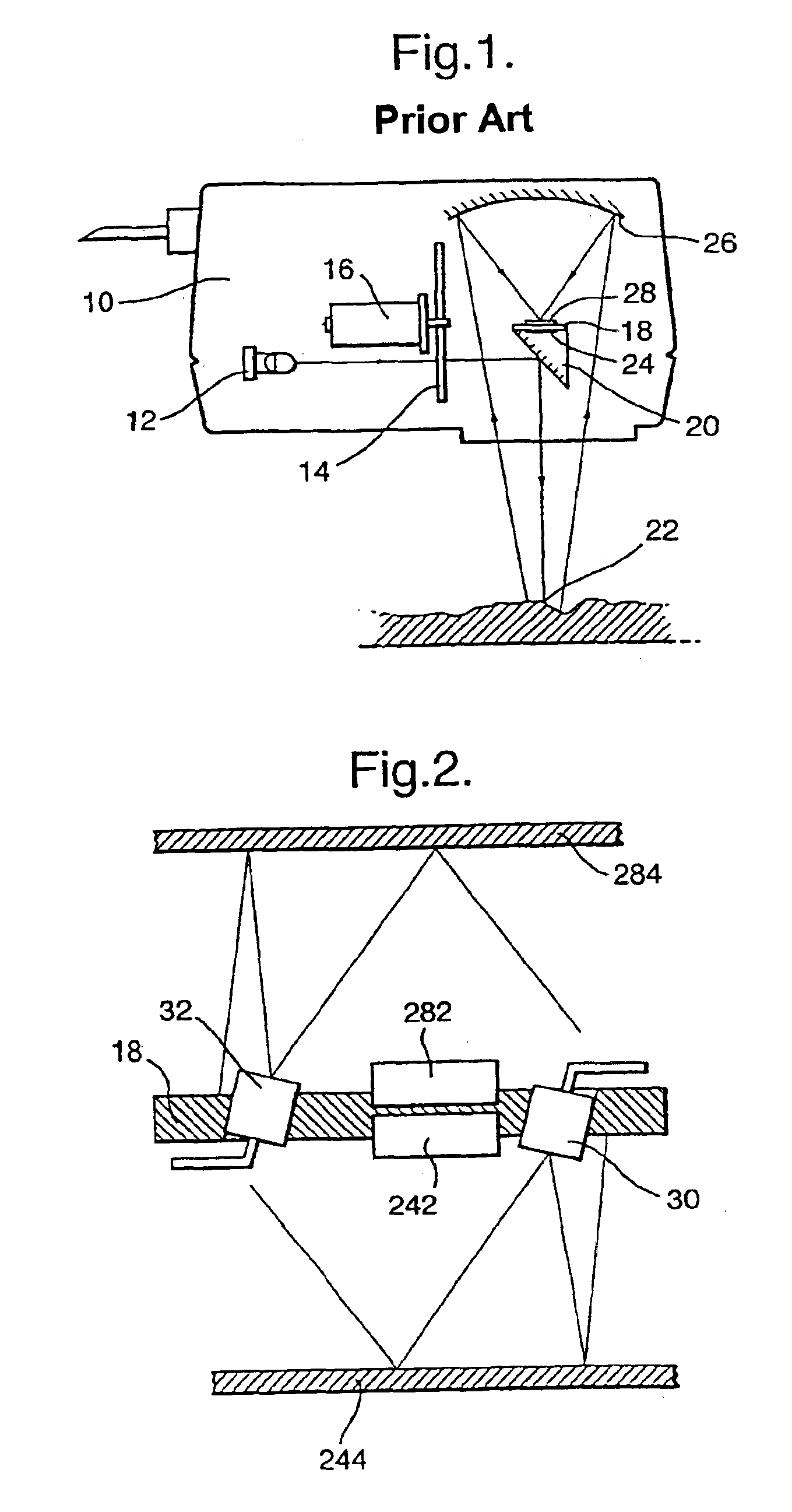
Referring initially to FIG. 1, this shows the head 10 of a known infrared gauge, for example as described in our published PCT application No. WO98 / 22806. The head 10 contains a lamp 12 providing a source of infrared radiation, and a circular filter wheel 14 driven by a motor 16. The filter wheel 14 carries a series of filters, for example 5 filters, and each filter is designed to pass a different selected emission Wavelength. The light passed by the respective filters is directed towards a detector mounting table 18, as described below.

The mounting table 18 carries a beam splitter 20 which reflects a portion of the light beam downwardly out of the infrared gauge 10 towards a sample 22. A remaining portion of the infrared light beam striking the beam splitter 20 is refracted within the beam splitter towards a detector assembly 24 including a photo-electric sensor. Meanwhile, the light emitted by the head 10 towards the sample 22 is reflected back from the sample 22 towards a collect...


PUM

PropertyMeasurementUnit
wavelengthsaaaaaaaaaa
temperatureaaaaaaaaaa

Abstract

An infrared absorption gauge includes a detector circuit including a detector for detecting electromagnetic radiation from a sample and for generating a signal representing the radiation received, and means for stabilizing a response characteristic of the detector to the radiation detected thereby, said stabilizing means having a GaAs diode for directing radiation at the detector and means for controlling the radiation source in dependence upon the signal generated by the detector. The stabilizing means thus acts as a negative feedback loop and seeks to maintain the overall illumination irradiating the detector (i.e. the combined illumination that is reflected back from the sample and that is emitted by the GaAs diode), at a substantially constant predetermined level, which tends to linearize and extend the frequency response of the detector to the radiation detected.

Description

TECHNICAL FIELDThe present invention relates to electromagnetic detection apparatus, and in particular to an electromagnetic gauge for measuring a parameter of a sample, especially an infrared absorption gauge.BACKGROUND ARTInfrared absorption gauges are well known and are used for example for measuring constituents of samples (e.g. the moisture content of paper or tobacco, or the fat, protein and water contents of foodstuffs), the amounts of substances absorbed or adsorbed on a substrate, the thickness of coatings or films on a substrate or the degree of cure of resins in a printed circuit board. In this specification, the term “parameter” is used to denote the property (composition, coating thickness etc.) of the sample being measured.Infrared absorption gauges conventionally operate by projecting infrared radiation at two or more wavelengths onto a sample or a substrate and measuring the intensity of the radiation reflected, transmitted or scattered by the sample. Signals proport...

Claims


Application Information

Patent Timeline
Patent Type & Authority Patents(United States)
IPC IPC(8): G01N21/27G01J1/32G01N21/25G01J1/10G01J1/16G01N21/35
CPCG01J1/1626G01N21/274G01J1/32G01N21/27
Inventor SKELTON, COLIN DAVID JOHN
Owner NDC INFRARED ENG
Why Eureka
Try Eureka