High-frequency, liquid metal, latching relay with face contact

a latching relay and liquid metal technology, applied in relays, generators/motors, contacts, etc., can solve the problems of solid contact relays, contact damage, deformation of conductivity, etc., and achieve high frequency switching, increase the gap, and facilitate manufacture

Inactive Publication Date: 2005-04-05
AGILENT TECH INC
View PDF101 Cites 4 Cited by
  • Summary
  • Abstract
  • Description
  • Claims
  • Application Information

AI Technical Summary

Benefits of technology

[0055]A high frequency electrical relay is disclosed that uses a conducting liquid in the switching mechanism. In the relay, two contacts are held a small distance apart. The facing surfaces of the contacts each support a droplet of a conducting liquid, such as a liquid metal. In an exemplary embodiment, a piezoelectric actuator is preferably energized to reduce the gap between the electrical contacts, causing the two conducting liquid droplets to coalesce and form an electrical circuit. The piezoelectric actuator is then de-energized and the electrical contacts return to their starting position. The liquid

Problems solved by technology

Rapid switching of high currents is used in a large variety of devices, but provides a problem for solid-contact based relays because of arcing when current flow is disrupted.
The arcing causes damage to the contacts and degrades their conductivity due to pitting of the electrode surfaces.
However, the use of heated gas has several disadvantages.
It requires a relatively large amount of energy to chan

Method used


Image

  • High-frequency, liquid metal, latching relay with face contact
  • High-frequency, liquid metal, latching relay with face contact
  • High-frequency, liquid metal, latching relay with face contact

Examples


Embodiment Construction

[0064]While this invention is susceptible of embodiment in many different forms, there is shown in the drawings and will herein be described in detail one or more specific embodiments, with the understanding that the present disclosure is to be considered as exemplary of the principles of the invention and not intended to limit the invention to the specific embodiments shown and described. In the description below, like reference numerals are used to describe the same, similar or corresponding parts in the several views of the drawings.

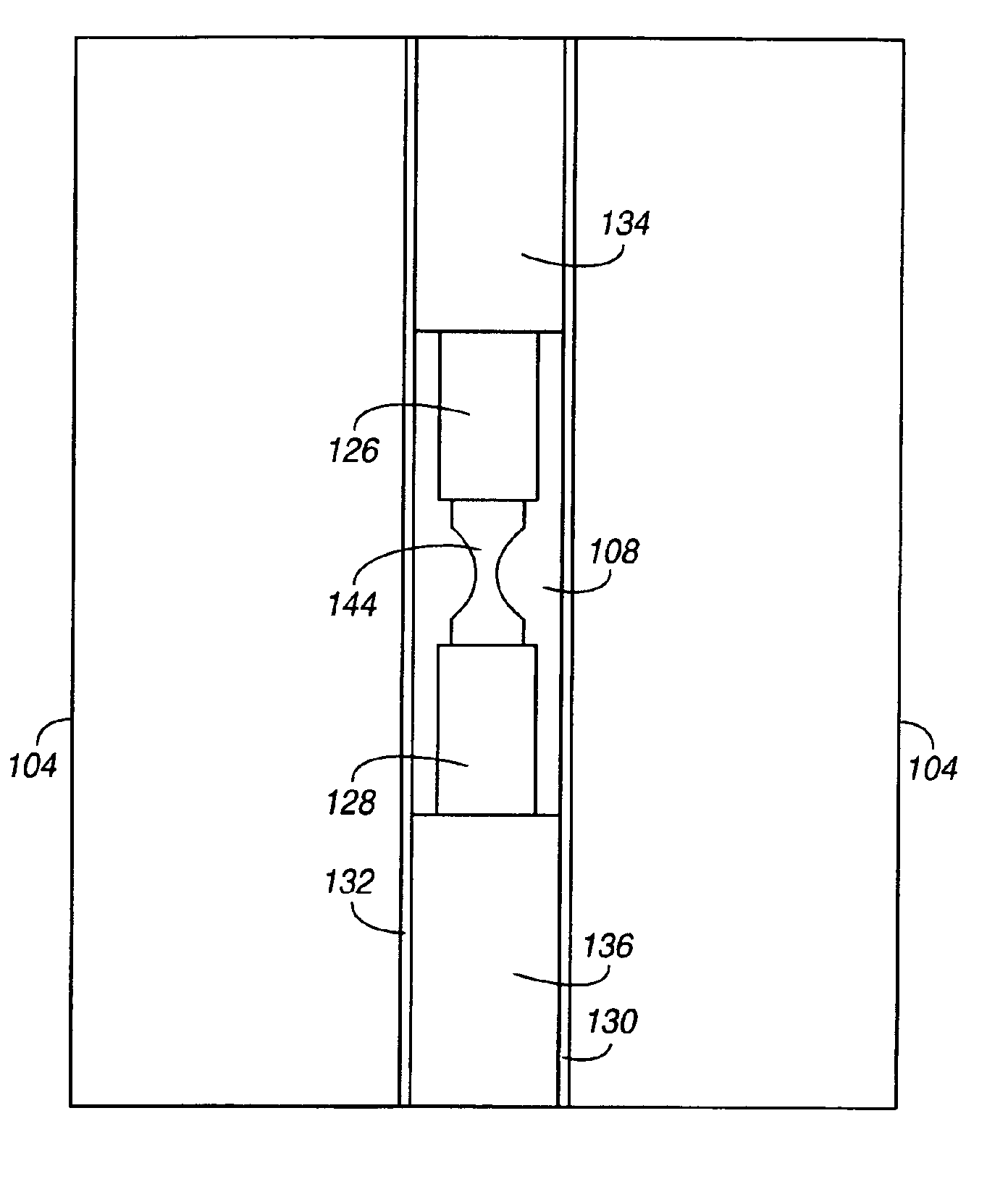
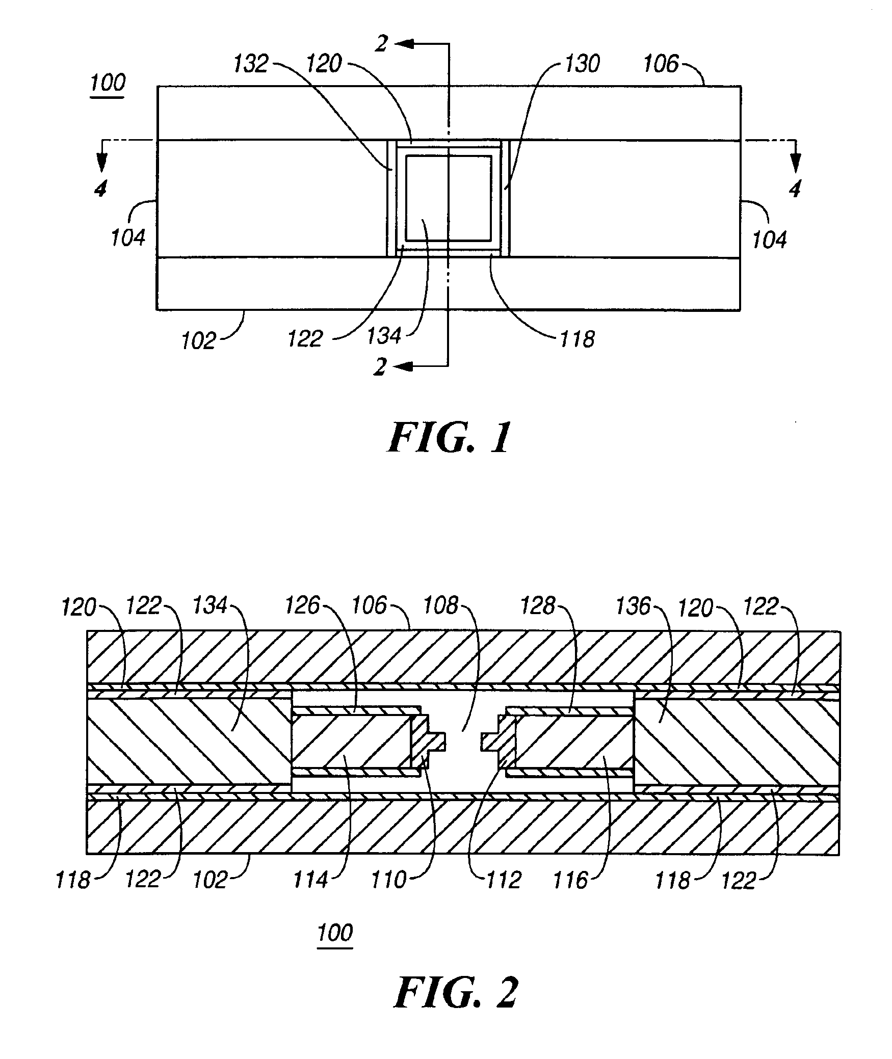
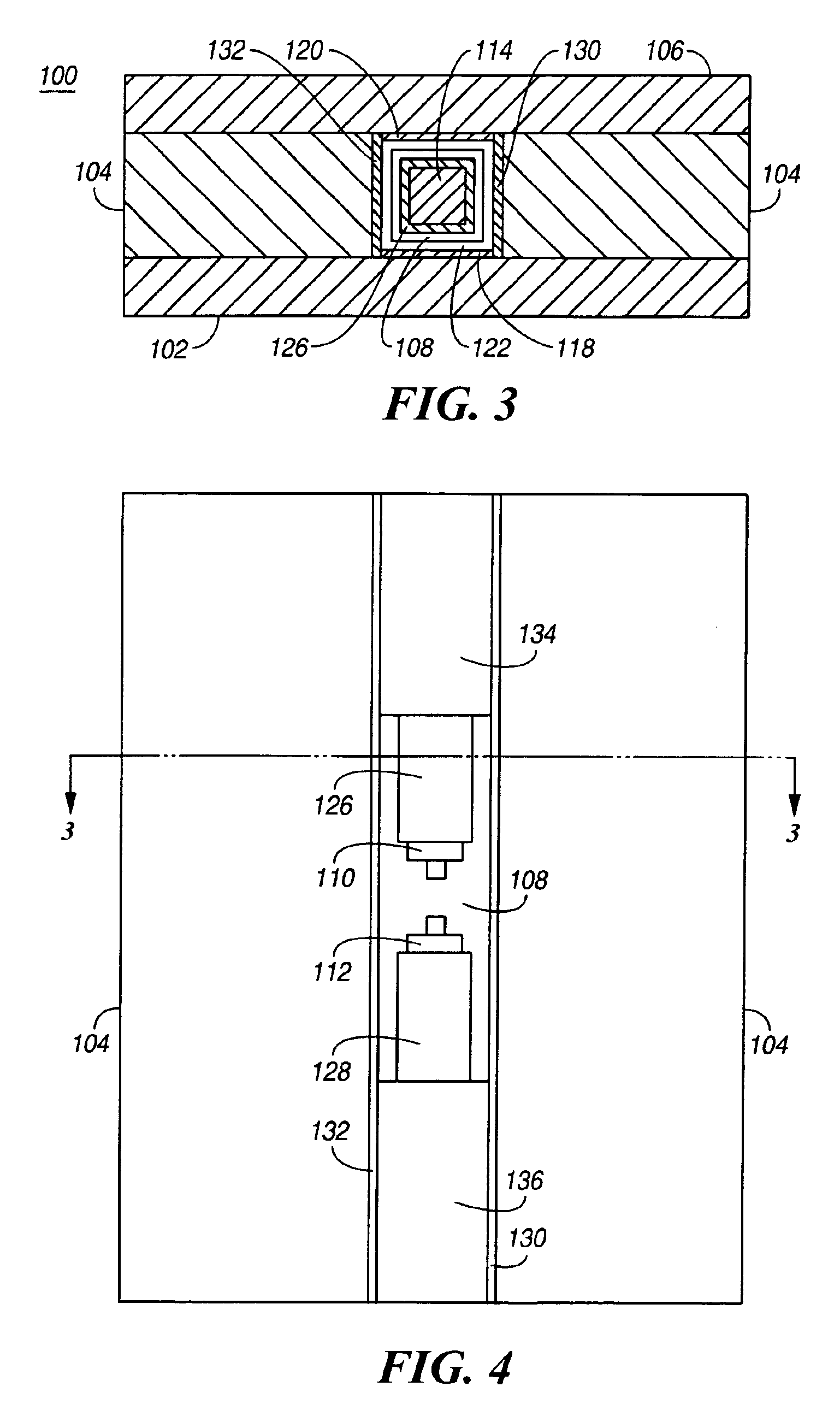
[0065]The electrical relay of the present invention uses a conducting liquid, such as liquid metal, to bridge the gap between two electrical contacts and thereby complete an electrical circuit between the contacts. The two electrical contacts are held a small distance apart. Each of the facing surfaces of the contacts supports a droplet of a conducting liquid. In an exemplary embodiment, the conducting liquid is preferably a liquid metal, such as merc...


PUM


Abstract

An electrical relay using conducting liquid in the switching mechanism. The relay is amenable to manufacture by micro-machining techniques. In the relay, two electrical contacts are held a small distance apart. The facing surfaces of the contacts each support a droplet of a conducting liquid, such as a liquid metal. An actuator is energized to reduce the gap between the electrical contacts, causing the two liquid metal droplets to coalesce and form an electrical circuit. The actuator is then de-energized and the electrical contacts return to their starting positions. The liquid metal droplets remain coalesced because of surface tension. The electrical circuit is broken by energizing an actuator to increase the gap between the electrical contacts and break the surface tension bond between the liquid metal droplets. The droplets remain separated when the piezoelectric actuator is de-energized because there is insufficient liquid metal to bridge the gap between the contacts. Additional conductors are included in the assembly to provide a coaxial structure and allow for high frequency switching.

Description

CROSS REFERENCE TO RELATED APPLICATIONS[0002]This application is related to the following co-pending U.S. patent applications, being identified by the below enumerated identifiers and arranged in alphanumerical order, which have the same ownership as the present application and to that extent are related to the present application and which are hereby incorporated by reference:[0003]Application 10010448-1, titled “Piezoelectrically Actuated Liquid Metal Switch”, filed May 2, 2002 and identified by Ser. No. 10 / 137,691;[0004]Application 10010529-1, “Bending Mode Latching Relay”, and having the same filing date as the present application;[0005]Application 10010531-1, “High Frequency Bending Mode Latching Relay”, and having the same filing date as the present application;[0006]Application 10010570-1, titled “Piezoelectrically Actuated Liquid Metal Switch”, filed May 2, 2002 and identified by Ser. No. 10 / 142,076;[0007]Application 10010572-1, “Liquid Metal, Latching Relay with Face Contac...

Claims


Application Information

Patent Timeline
IPC IPC(8): H01H1/08H01H29/02H01H55/00H01H57/00
CPCH01H57/00H01H2001/0042H01H2029/008H01H2057/006H01H29/02H01H55/00
Inventor WONG, MARVIN GLENN
Owner AGILENT TECH INC
Why Eureka
Try Eureka