Video signal conversion device and video signal conversion method

Inactive Publication Date: 2005-04-05
PANASONIC CORP
View PDF22 Cites 27 Cited by
  • Summary
  • Abstract
  • Description
  • Claims
  • Application Information

AI Technical Summary

Benefits of technology

In this case, it is possible to simultaneously reset the third and fourth counters outputting the reference pulse for the PLL circuit and a feedback pulse, whereby an oscillating operation of this PLL circuit can be stabilized.

Problems solved by technology

Vertical frequency conversion is processing of converting the vertical frequency of a video signal to a vertical frequency suitable to the display device, and it is most desirable to set the vertical frequency to 60 Hz due to limitation of a gradation representation technique in the PDP and due to limitation of the gradation representation technique and the operating speed thereof in the liquid crystal panel.

Method used


Image

  • Video signal conversion device and video signal conversion method
  • Video signal conversion device and video signal conversion method
  • Video signal conversion device and video signal conversion method

Examples


first embodiment

(First Embodiment)

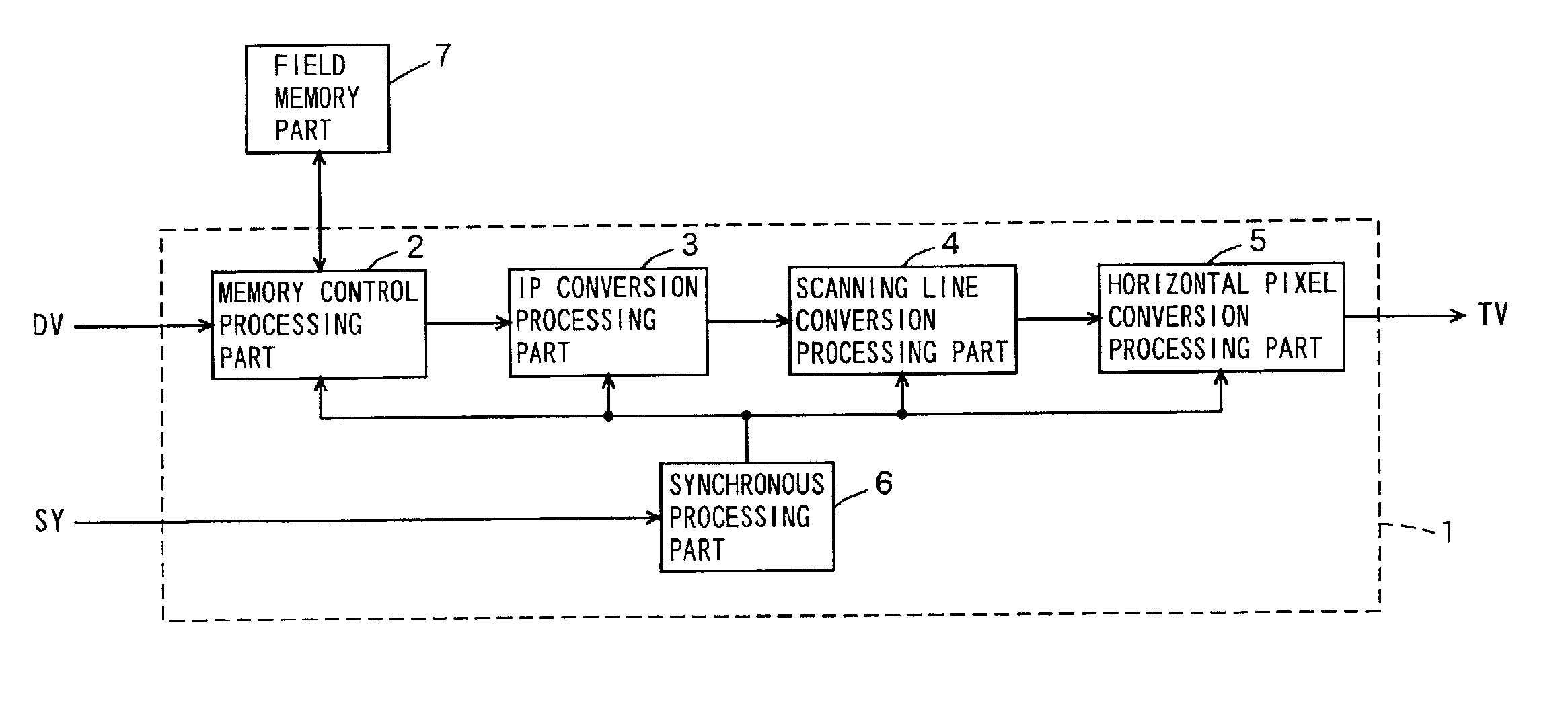
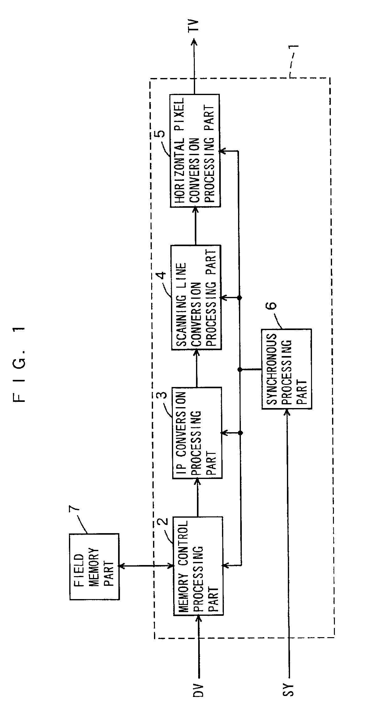
First, a video signal conversion device according to a first embodiment of the present invention is described. FIG. 1 is a block diagram showing the structure of the video signal conversion device according to the first embodiment of the present invention.

The video signal conversion device shown in FIG. 1 comprises a pixel converter 1 and a field memory part 7. The pixel converter 1 includes a memory control processing part 2, an I / P (interlace-to-progressive) conversion processing part 3, a scanning line conversion processing part 4, a horizontal pixel conversion processing part 5 and a synchronous processing part 6.

The memory control processing part 2, in which a video signal DV digitized by an A / D (analog-to-digital) converter (not shown) outside the device is input, generates a control signal for write and read addresses or the like and outputs the same to the field memory part 7, for performing transfer of the video signal with the field memory part 7.

The I / P ...

second embodiment

(Second Embodiment)

When structuring a video signal conversion device performing vertical frequency conversion, I / P conversion, scanning line conversion and horizontal pixel conversion, a plurality of clocks, a horizontal synchronizing signal and a vertical synchronizing signal are required as synchronizing signals in order to properly control operations of each block.

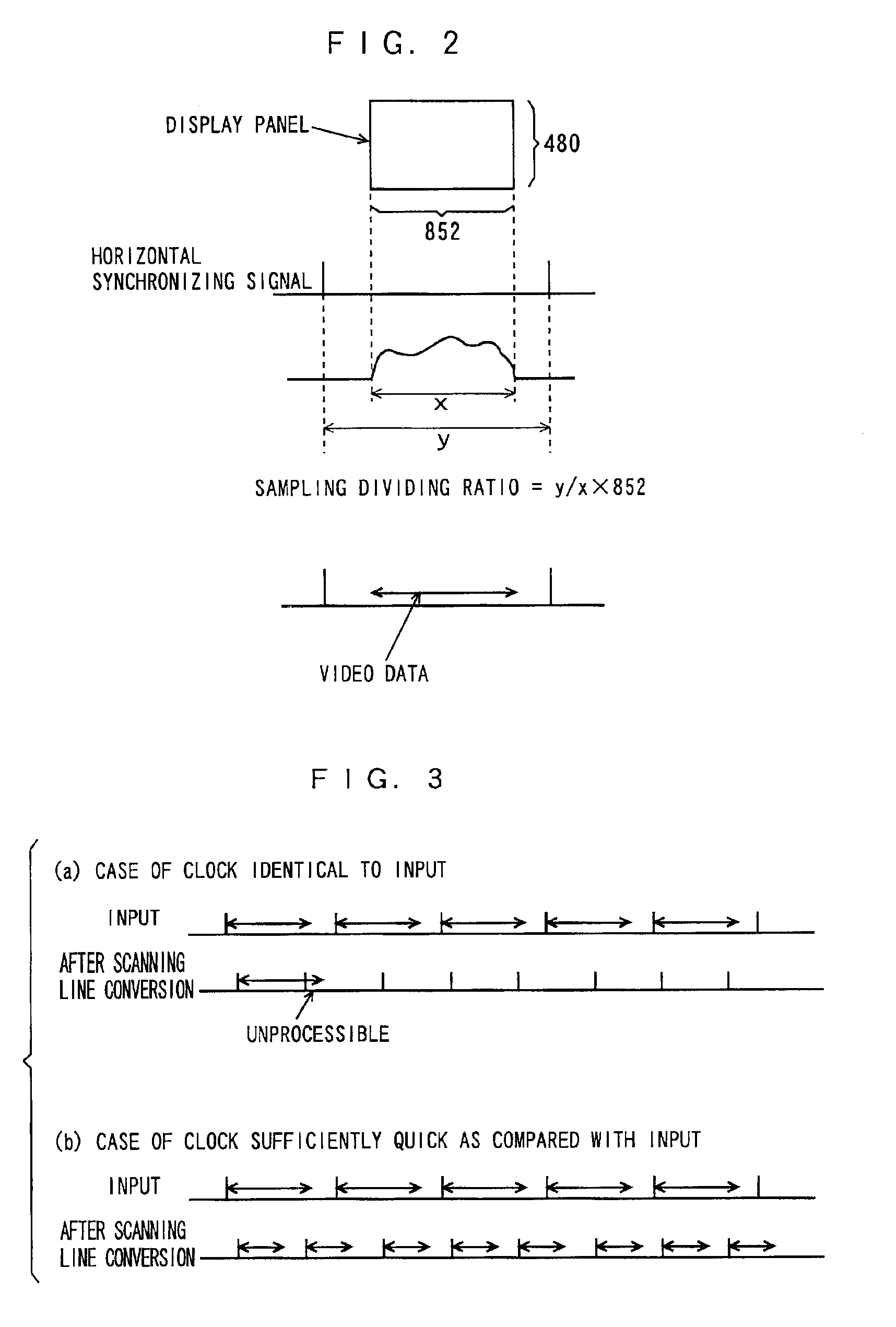
First, the clocks are described. A clock on the input side of the video signal conversion device is synchronized with a digitized video signal, and becomes the same clock as a sampling clock of an A / D converter, outside the device, converting an analog video signal to a digital video signal. As to this sampling clock, the dividing ratio of the sampling clock is y / x x×852 from a horizontal scanning period y and an effective image period x in the case of a display panel having 852 pixels in the horizontal direction as shown in FIG. 2, and the larger part of the horizontal scanning period forms an image period filled with ...

third embodiment

(Third Embodiment)

A third Embodiment of the present invention is now described. This embodiment performs scanning line conversion when performing neither vertical frequency conversion nor conversion of horizontal frequencies (from the frequency of a first latched horizontal synchronizing signal H12 to the frequency of a second horizontal synchronizing signal H21) before and after a field memory.

When performing expansion processing of 2→3 conversion as scanning line conversion, for example, a third horizontal synchronizing signal H31 after scanning line conversion has a frequency of 1.5 times that of a first horizontal synchronizing signal H11. In this case, that of 1.5 times is simply required also as to a clock frequency on the output side, and a circuit capable of coping with a high frequency is required for a next-stage circuit. When performing 3→2 conversion as reduction processing, on the other hand, the number of lines of the third horizontal synchronizing signal H31 after con...


PUM


Abstract

Video data of a field necessary for I/P conversion and scanning line conversion is stored in a field memory part (7), vertical frequency conversion is performed by a memory control processing part (2), I/P conversion is performed by an I/P conversion processing part (3), scanning line conversion is performed by a scanning line conversion part (4) and horizontal pixel conversion is performed by a horizontal pixel conversion processing part (5) with the data stored in the field memory part, and a synchronous processing part (6) supplies a prescribed clock, a horizontal synchronizing signal and a vertical synchronizing signal to each block. A single system performs vertical frequency conversion, I/P conversion, scanning line conversion and horizontal pixel conversion.

Description

TECHNICAL FIELDThe present invention relates to a video signal conversion device and a video signal conversion method converting a video signal to a video signal suitable to a display device, and more particularly, it relates to a video signal conversion device and a video signal conversion method converting a video signal to a video signal suitable to a display device performing matrix display.BACKGROUND ARTThere are a PDP (plasma display panel) and a liquid crystal panel etc. as dot matrix display panels, and I / P (interlace-to-progressive) conversion, scanning line conversion, horizontal pixel conversion and vertical frequency conversion can be listed as signal processing techniques necessary and inevitable for these display panels.I / P conversion is processing of converting an interlace signal to a progressive signal. Scanning line conversion is processing of performing vertical expansion processing and reduction of a display image. Horizontal pixel conversion is processing of per...

Claims


Application Information

Patent Timeline
Patent Type & Authority Patents(United States)
IPC IPC(8): H04N7/01H04N5/44H04N5/46G09G3/20G09G5/00G09G5/36G09G5/391
CPCH04N7/01H04N7/0135H04N7/012H04N7/0105H04N5/46H04N21/440218
Inventor MUTO, YASUAKIWAKAHARA, TOSHIONIWA, AKIOHIGASHI, TAKUMAMORITA, TOMOKOSEKIGUCHI, YUJI
Owner PANASONIC CORP
Why Eureka
Try Eureka