

Portable drag compressor powered mechanical ventilator
a mechanical ventilator and compressor technology, applied in the field of medical equipment, can solve the problems of inability to deliver complex ventilation modes and or breath types, inconvenient portability, and inability to meet the needs of long-term ventilation or long-term ventilation, and achieve the effect of minimizing fabrication inaccuracy and accurately measuring patient exhalation flow
- Summary
- Abstract
- Description
- Claims
- Application Information
AI Technical Summary
Benefits of technology
Problems solved by technology
Method used
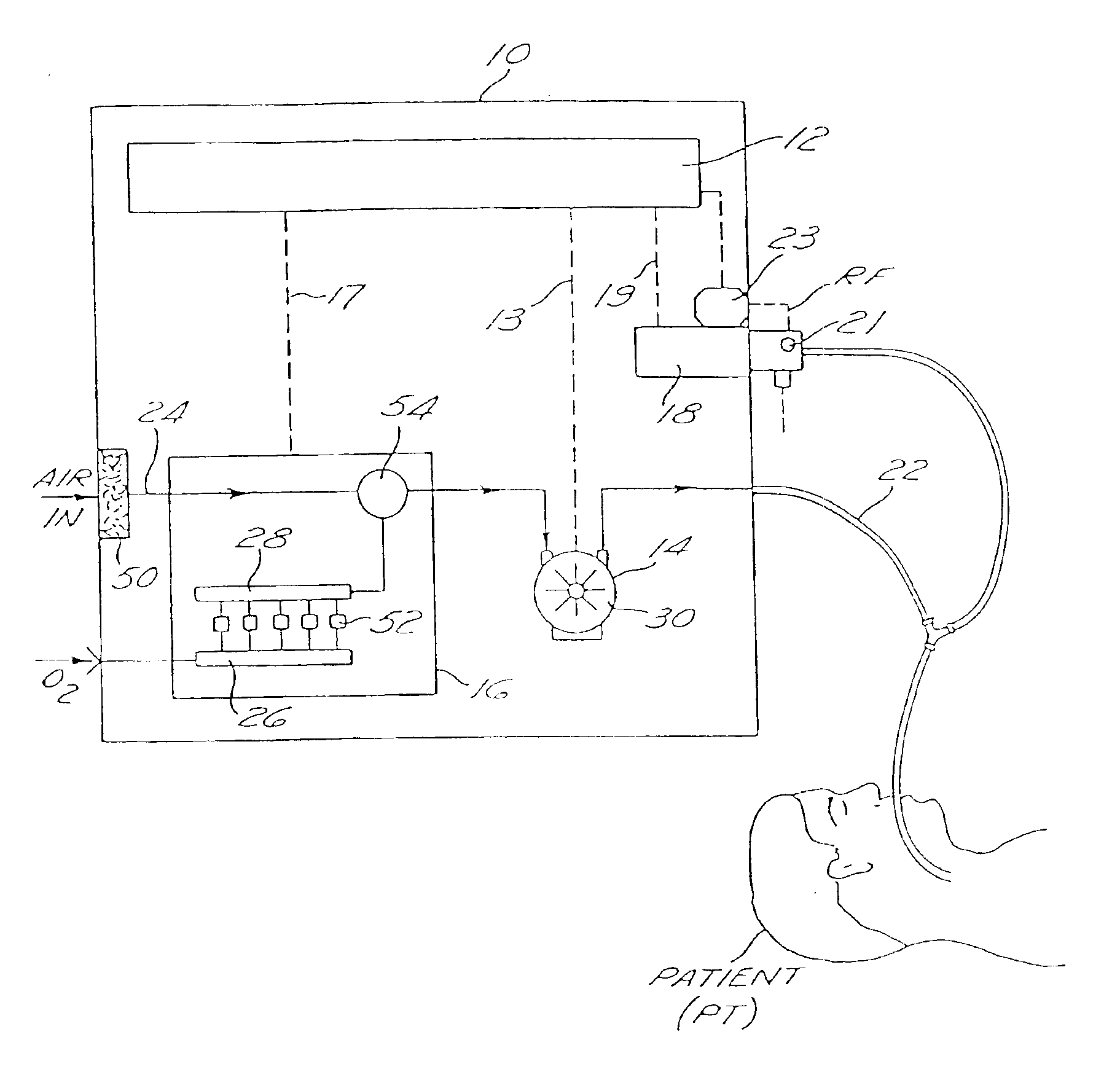
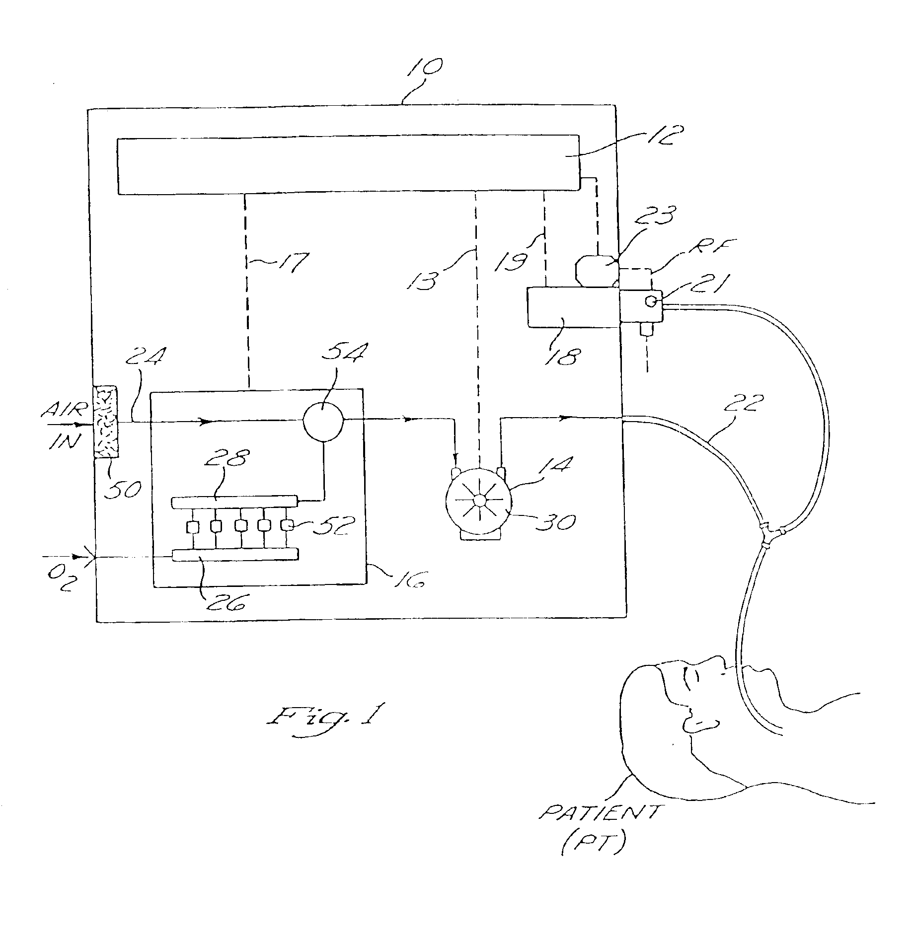
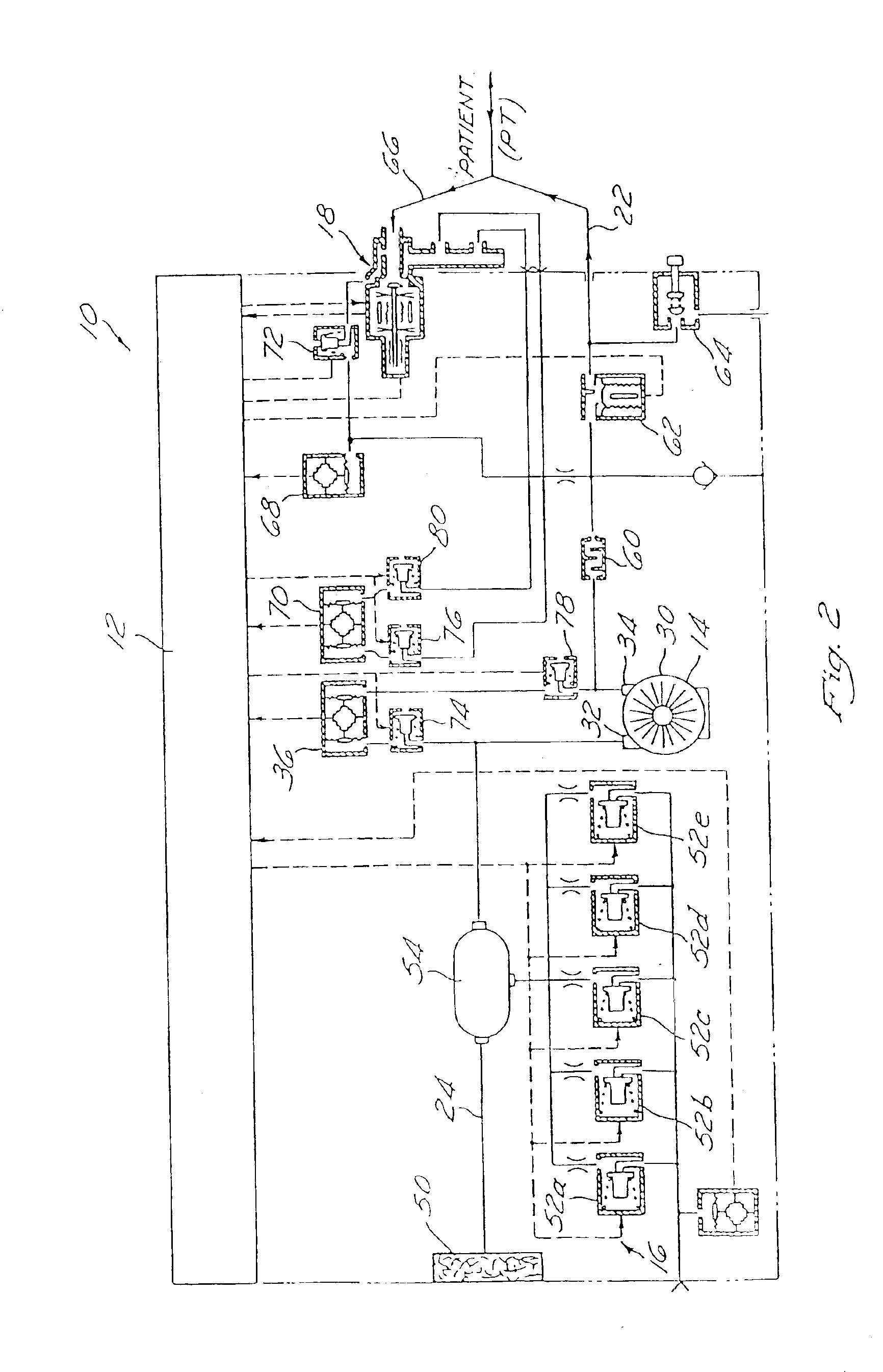
Image

Examples
example
Delivery of 0.6 Fio2 Using 4 Solenoids
In this example, the oxygen blending apparatus has 4 solenoids with flows of 5 lpm, 15 lpm, 40 lpm, and 80 lpm respectively. The FiO2 setting is 60%, thus the trigger volumes for each of the 4 solenoids is 8 ml, 25 ml, 66 ml, and 133 ml respectively. Furthermore a constant oxygen inlet pressure is assumed resulting in an “on” time of 100 ms for the solenoids, a constant compressor flow of 60 lpm, and a period of 1 ms. The following table describes the state of the oxygen blending algorithm after various iterations:
SolenoidSolenoidSolenoidSolenoidAccumulated1234Time (ms)Volume (ml)(8 ml)(25 ml)(66 ml)(133 ml)00offoffoffoff11offoffoffoff22offoffoffoff* * *77offoffoffoff80onoffoffoff91onoffoffoff* * *3224offoffoffoff330ononoffoff341ononoffoff* * *9865ononoffoff990onononoff1001onononoff* * *1078onononoff1081off > on*ononoff*At 108 ms the 8 ml solenoid turned off after having been on for 100 ms, but since the accumulated volume is now 9 ml the soleno...
PUM
 Abstract
Description
Claims
Application Information