Heat storage device

a heat storage device and heat storage technology, applied in the field of heat storage devices, can solve the problems of large heat loss within the heat storage material, marked reduction in heat storage efficiency, and inability to be widely changed by nature, so as to accelerate heat transfer, speedily execute a heat transfer, and execute quickly and efficiently

Inactive Publication Date: 2005-04-12
NAT INST OF ADVANCED IND SCI & TECH
View PDF9 Cites 9 Cited by
  • Summary
  • Abstract
  • Description
  • Claims
  • Application Information

AI Technical Summary

Benefits of technology

In addition, in the present invention, means for promoting heat transfer is provided between the central portion and the outer portion in the heat storage tank. When, for example, a rapid injection to and an extraction from the heat storage tank is required, it is possible to speedily execute a heat transfer between the central portion and the outer portion where the heat transfer from the central portion is difficult due to the suppression means against natural convection.
The heat exchange means in the present invention can be disposed so that the central portion and the outer portion in the heat storage tank are caused to sequentially perform a heat exchange with the outside. By this constitution, when injecting heat, by utilizing the residual heat remaining after the heating or cooling of the central portion in the heat storage tank, it is possible to additionally heat or cool the outer portion. On the contrary, when extracting heat, after the preheating or precooling of the heat exchanger in the outer portion in the heat storage tank, it is possible to additionally heat or cool the heat exchanger in the outer portion. This allows the exchange of heat between the heat storage device and the external environment to be executed rapidly and efficiently.
Moreover, the heat exchange means can be disposed so that the central portion and the outer portion in the heat storage tank are caused to individually perform a heat exchange with the outside. By this constitution, when injecting heat, a heat exchange can be executed in the central portion or the outer portion whichever is more suitable, in accordance with the temperature of the heat injected from the outside to the heat storage tank. On the contrary, when extracting heat, a heat exchange may be executed in the central portion or the outer portion whichever is more suitable, in accordance with the temperature of the heat required by the outside. Consequently, the exchange of heat between the heat storage device and the external environment can be executed rapidly and efficiently.
In accordance with the above-described heat storage devices associated with present invention, since the ease of convection of the heat storage material or heat transfer medium within the heat storage tank varies depending on position, the injection operation from the ou...

Problems solved by technology

However, the greater is the temperature difference between the surface temperature Tx′ of the heat storage material and the ambient temperature T0 in the outside, and also the longer is the storage time, the larger the heat loss represented in the equation (2) becomes, which results in a marked reduction in heat storage efficiency.
However, since the time term and temperature term in the equation (2) are associated with the original purpose of the heat storage, they can not be widely changed by nature.
Consequently, heat storage material having a temperature closer to the temperature of external environment rather than to the heat stored flows from t...

Method used


Image

  • Heat storage device
  • Heat storage device
  • Heat storage device

Examples


embodiment 1

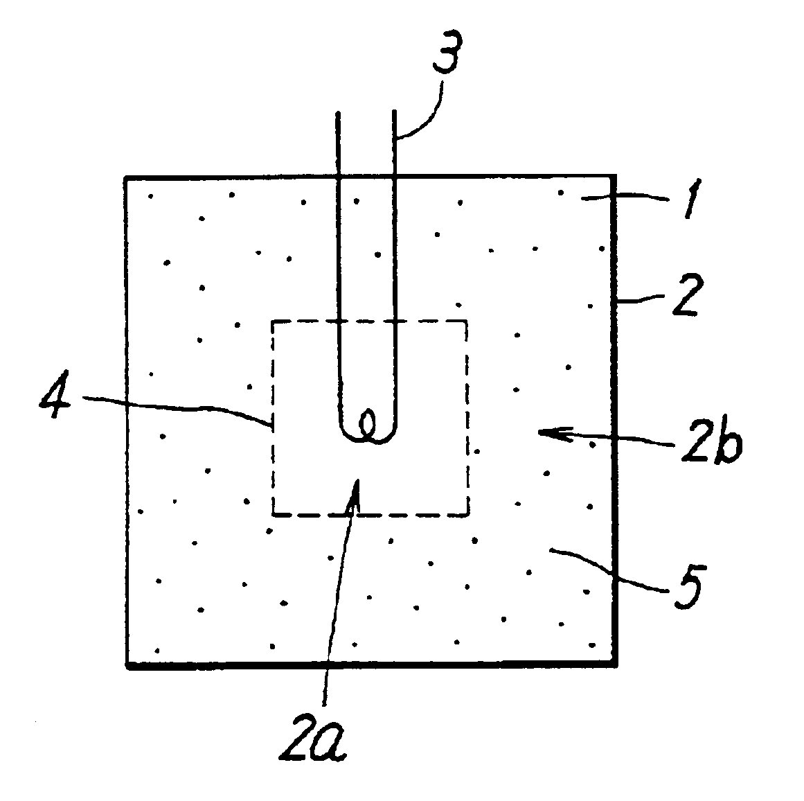
FIG. 1 is an embodiment of sectional view of the heat storage device in accordance with the present invention. This heat storage device accommodates a heat storage material 1 for storing heat in a heat storage tank 2 and has a heat exchanger 3 in a heat storage tank 2, as means for executing a heat exchange with the outside. As a heat storage material 1, various materials may be used in accordance with a required heat storage temperature. The heat storage material 1 may be a material which makes a phase change in the processes of injection and extraction of heat. The inside space of the heat storage tank is divided by a net 4 into a central portion 2a and an outer portion 2b surrounding the central portion 2. That is, within the heat storage tank 2, the net 4 is stretched throughout the boundary between the central portion 2a and the outer portion 2b, and the central portion 2a is surrounded by the outer portion 2b via the net 4. A liquid-absorbent material 5 is dispersed only in th...

embodiment 2

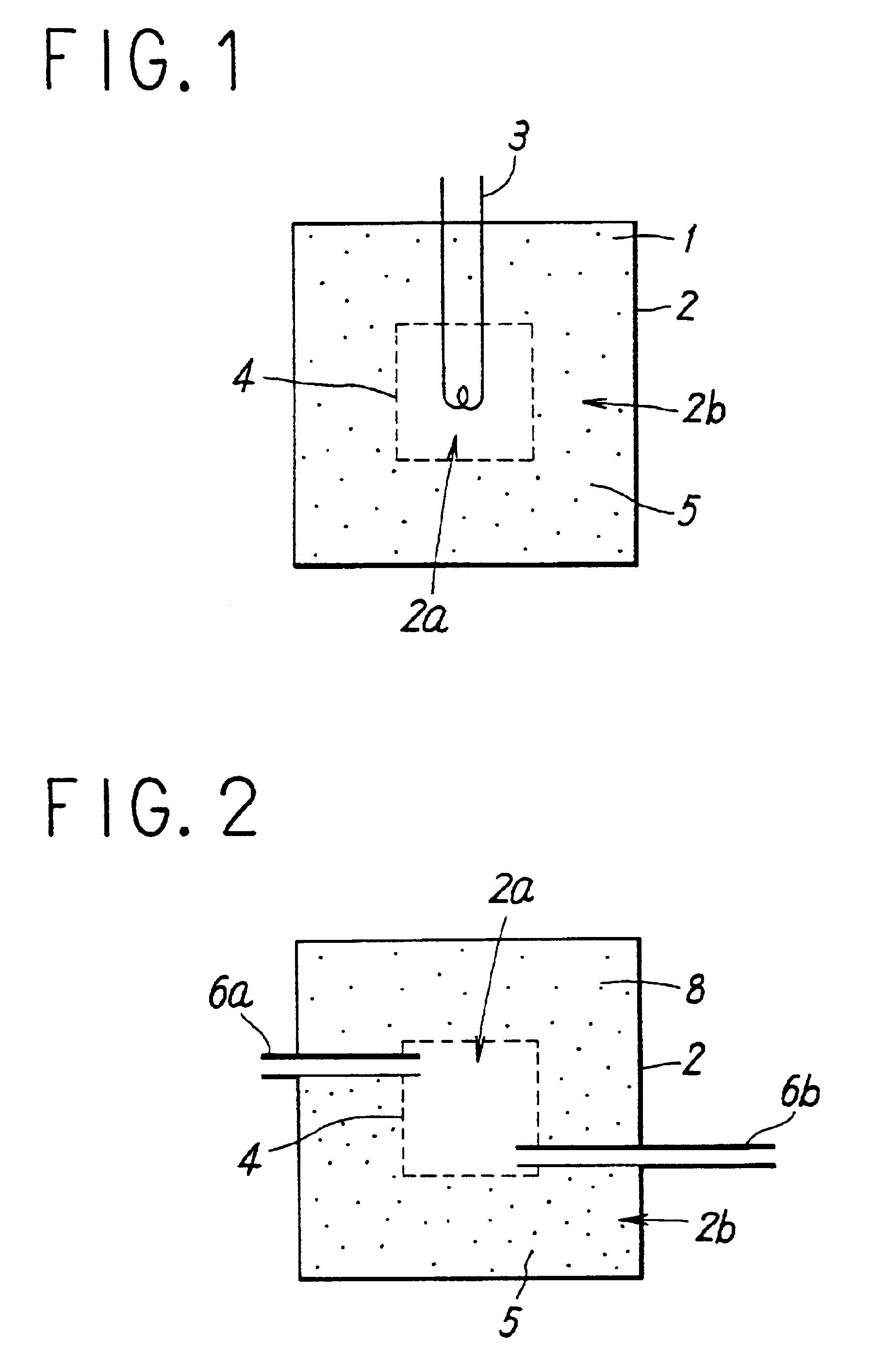
FIG. 2 is a sectional view of another embodiment of the heat storage device in accordance with the present invention. This heat storage device accommodates a heat transfer medium 8 which also serves as a heat storage material, in a heat storage tank 2. However, unlike the case of FIG. 1, this heat storage device makes communicate the central portion 2a surrounded by a net 4 in the heat storage tank 2, with the outside of the heat storage device by two communicating tubes 6a and 6b which execute the inflow and outflow of the transfer medium 8. The other constructions are similar to the embodiment shown in FIG. 1.

Next, a description is presented of the operation of the heat storage device in the case where a higher temperature than that of the external environment is stored in the heat storage device shown in FIG. 2.

In the injection process of heat, the heat transfer medium 8 sucked out from the communicating tube 6b is heated by a heat source at the outside, and is circulated back to...

embodiment 3

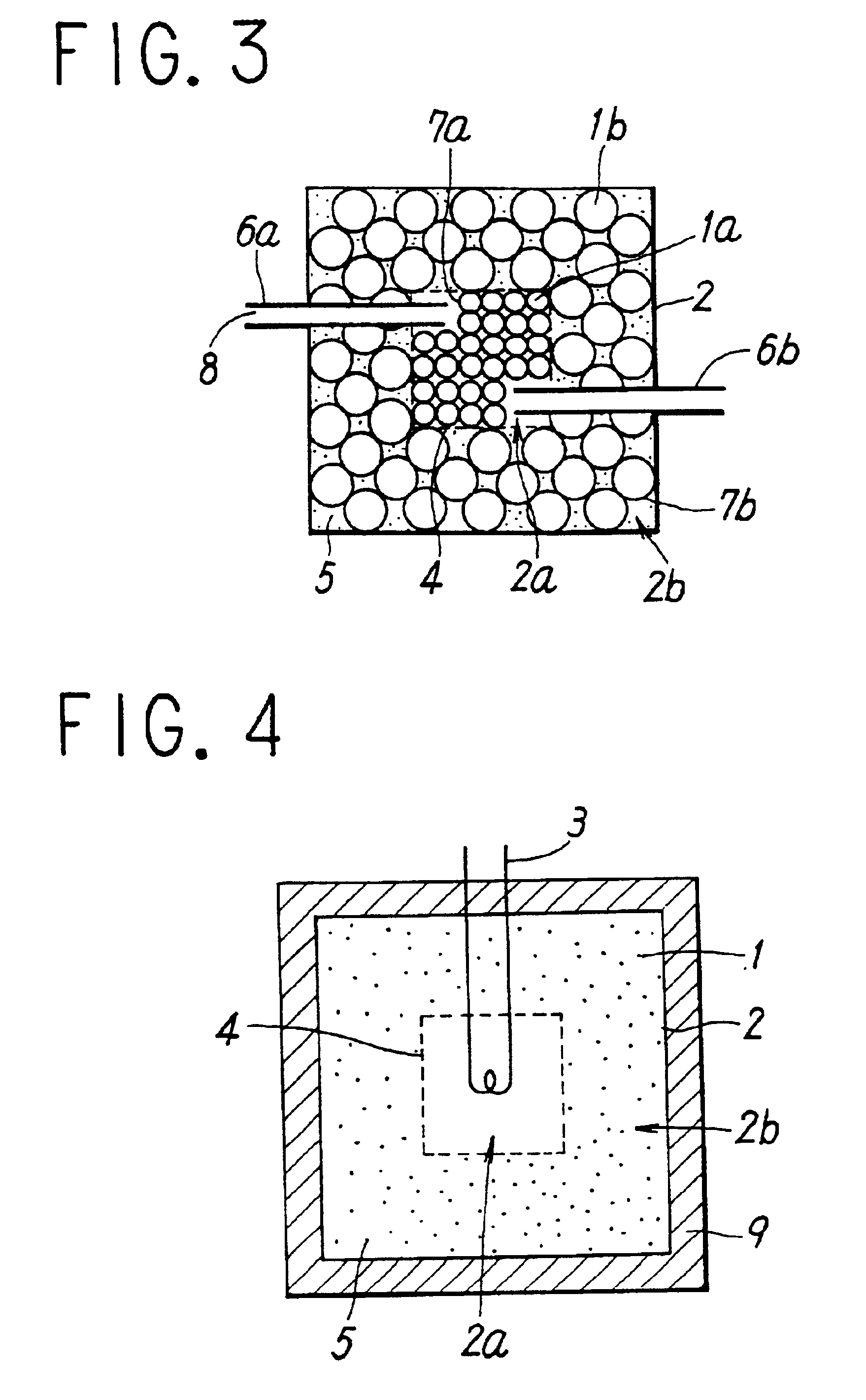
FIG. 3 is a sectional view of another embodiment of the heat storage device in accordance with the present invention. In this heat storage device, in a heat storage tank 2 having a similar construction as the embodiment shown in FIG. 2, heat storage materials 1a and 1b to be accommodated in the central portion 2a and the outer portion 2b are accommodated in small vessels 7a and 7b, respectively. As heat storage materials 1a and 1b, various materials may be used in accordance with required temperatures. The heat storage material may be a material which makes a phase change in the processes of injection and extraction. Further, the heat storage materials 1a and 1b which exist respectively in the central portion 2a and the outer portion 2b in a heat storage tank 2 may be an identical material, or may be different materials.

In the drawing, though small vessels 7a and 7b in this embodiment are represented by a spherical shape, the material and shape of the small vessel are not limited, a...


PUM


Abstract

A heat storage device comprises a heat storage tank 2 charged with a heat storage material 1 for storing the heat supplied from the outside, and a heat exchanger 3 for executing an injection and an extraction of heat between the inside of the storage tank2 and the outside by the heat exchange between the heat storage material and a heat transfer medium. The heat exchanger 3 is disposed so as to execute a heat exchange between the central portion 2a in the heat storage tank 2 and the outside, and suppresses the natural convection of the heat storage material 1 of the outer portion 2b by, for example, dispersing a liquid-absorbent material 5 in the outer portion 2b surrounding the central portion in the heat storage tank 2, whereby reduces the influence of external environment on the central portion 2a in the heat storage tank, thereby suppressing the heat loss toward the outside.

Description

FIELD OF THE INVENTIONThe present invention relates to a heat storage device for temporarily storing heat.DESCRIPTION OF THE RELATED ARTBasic constructions of conventional heat storage devices are illustrated in FIGS. 11 through 13 in the form of sectional views.A heat storage device shown in FIG. 11 comprises a heat storage tank 32 charged with a heat storage material 31 such as water, and a heat exchanger 33 disposed in the heat storage tank 32, for executing a heat exchange with the outside. In order to store the heat of, for example, a temperature Tx within this heat storage device, the temperature of the heat storage material 31 is raised to Tx by adding the heat of a temperature of at least Tx to the heat exchanger 33 from the outside. When heat is needed at the outside, the heat of the temperature Tx is extracted from the heat storage material 31 to the outside, using the heat exchanger 33.A heat storage device as shown in FIG. 12 comprises heat storage tanks 42a and 42b char...

Claims


Application Information

Patent Timeline
IPC IPC(8): F28D20/00
CPCF28D20/0056Y10S165/902Y02E60/142Y02E60/14
Inventor HIRANO, SATOSHI
Owner NAT INST OF ADVANCED IND SCI & TECH
Why Eureka
Try Eureka