Surface aeration impellers

a surface aeration and impeller technology, applied in the direction of liquid fuel engines, marine propulsion, vessel construction, etc., can solve the problems of insufficient understanding of the fundamental mass transfer mechanism and fluid dynamics of surface aeration, insufficient oxygen mass transfer analysis of current state-of-the-art surface aerator oxygen mass transfer analysis, and obvious limitation of solid suspension, so as to improve gas entrainment and oxygen transfer, the effect of efficient spraying liquid

Inactive Publication Date: 2005-04-12
MIXING & MASS TRANSFER TECH
View PDF11 Cites 38 Cited by
  • Summary
  • Abstract
  • Description
  • Claims
  • Application Information

AI Technical Summary

Benefits of technology

[0020]It is a still further object of the present invention to provide improved surface aeration impellers which may have camber and may be of air foil shape.
[0021]The invention is an improved surface aeration impeller for use in a liquid filled tank which efficiently sprays liquid and improves gas entrainment and oxygen transfer into the liquid surface. The impeller is an axial flow impeller and may be either a pitched blade turbine (PBT) or have airfoil shaped blades. In either case, the impeller has a portion which extends radially along an edge thereof which projects above the surface of the liquid being mixed in a vertical direction. The blades of the impeller are modified to include a top horizontal portion of the blade which tends to lower the spray of the liquid and an optional endcap, both of which simultaneously enhance and increase the standard aeration efficiency. Preferably, the impeller is rotated in an up-pumping direction and propels the liquid being aerated in a radially upward and outward direction. A sufficient upward surge of liquid is produced so that the liquid is observed to splash back onto the surface a plurality of times in the course of operation of the impeller. Such multiple splashing action enhances the contact between the air and the liquid itself to improve the efficiency of aeration.

Problems solved by technology

The problem of solids suspension, however, has an obvious limitation because of the remoteness of the surface aeration impeller from the tank bottom where the biomass solids tend to settle if the bulk liquid in the tank is not adequately mixed.
Many of the limitations associated with prior art surface aerator impeller designs result from an insufficient understanding of the fundamental mass transfer mechanisms and fluid dynamics of surface aeration.
The current state-of-the-art oxygen mass transfer analysis for surface aerators is essentially limited to the simple, idealized model employed in the ASCE Standard for the Measurement of Oxygen Transfer in Clean Water.
This design primarily focuses on spraying the liquid and does not provide much up-pumping action or mixing of the tank liquid content resulting in relatively low efficiency of the system.
However, this impeller still leaves room for improved liquid pumping and oxygen transfer efficiency.
Although these above-described surface aeration impellers have accomplished their purposes, problems remain regarding excessive splashing and misting, insufficient liquid pumping, and overflow of liquid over the surface aerator blades during operation.
One problem in particular with some prior art surface aeration impellers is that at the liquid submergence levels of the blades for normal operation as surface aerators, a significant quantity of liquid overflows the upper or leading edge of the blades and falls back into the impeller itself without being pumped and sprayed beyond the outer periphery of the impeller blades.
The amount of liquid which is moved per unit of energy input (the hydraulic efficiency) of the impeller is adversely affected due to the flow of liquid over the top of the blade characterizing the normal PBT turbine surface aeration impeller operation.
In addition, the overflow of liquid over the leading edge of the blades is believed to overload or flood the impeller with liquid which creates a hydraulic condition detracting from its hydraulic pumping capacity and oxygen transfer efficiency.

Method used


Image

  • Surface aeration impellers
  • Surface aeration impellers
  • Surface aeration impellers

Examples


Embodiment Construction

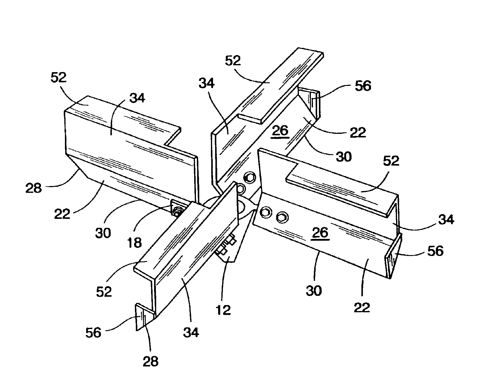
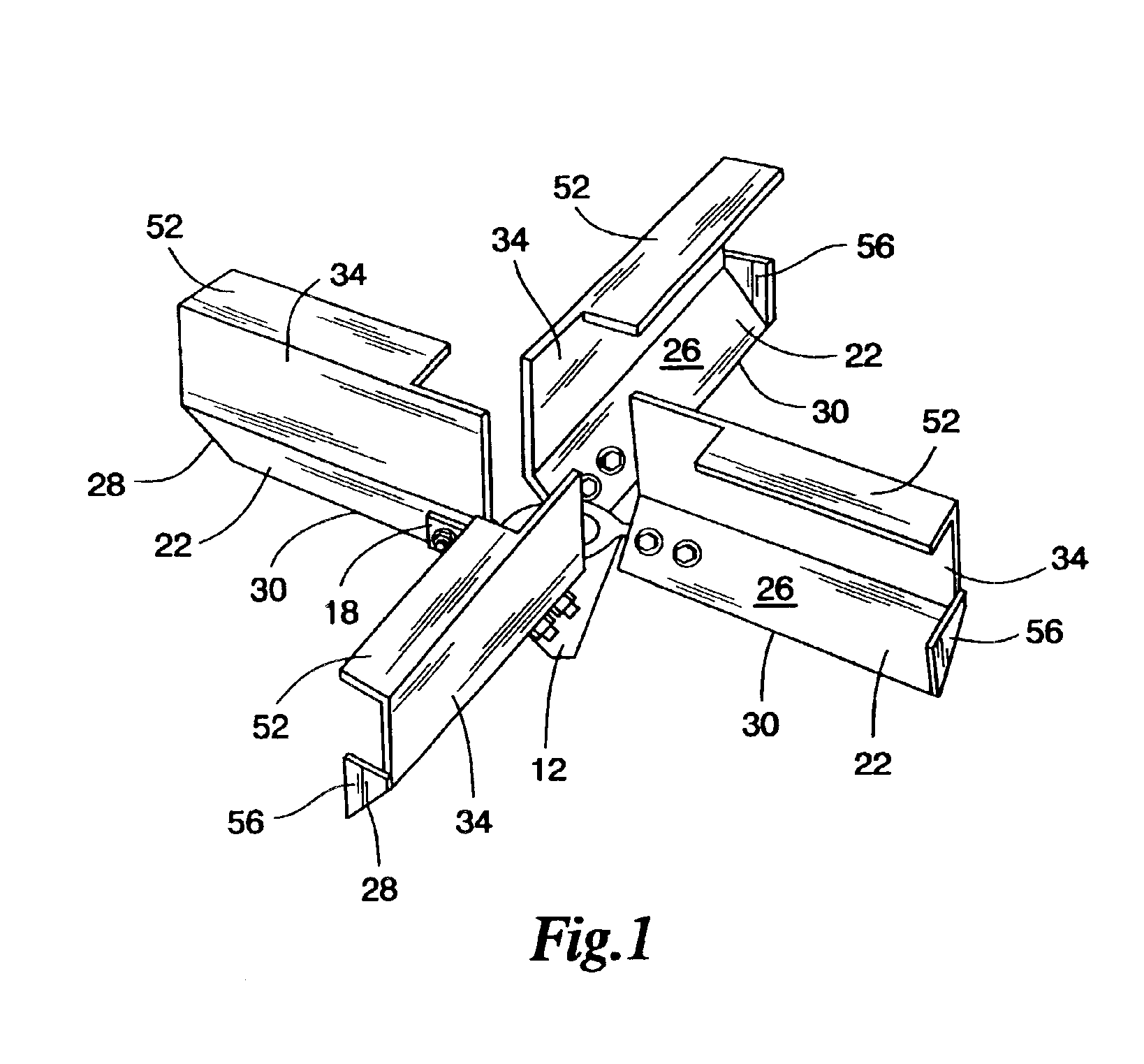
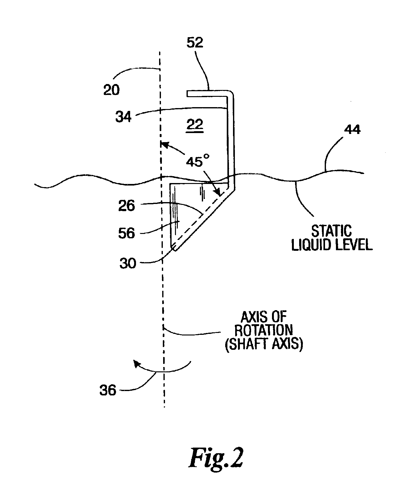
[0026]Referring to FIGS. 1-4 there is shown a shaft 10 having a hub 12 attached thereto by set screws and a key. The hub therefore rotates with the shaft. The hub has four arms 18 which are tilted at an angle (45°) with respect to the axis of rotation 20. Four blades 22 are attached to the arms 18 by groups of bolts and nuts. The number of bolts and nuts in the group depends upon the dimensions of the impeller. Other attachment means, such as weldments may be used for attaching the blades 22 to the hub 12.

[0027]The blades have lower portions 26 which are preferably rectangular plates having an outer edge 28 at the radially outward ends of the blades between the generally radially extending edge 30 and the generally radially extending joint between the lower portion 26 and the upper portion 34. The blade outer edges 28 are at 45° with respect to the shaft axis 20 in this example. However, this angle can be in the range of about 30° to 60° preferably about 40° to 50° and most preferab...


PUM

PropertyMeasurementUnit
angleaaaaaaaaaa
angleaaaaaaaaaa
chord angleaaaaaaaaaa

Abstract

The invention is an improved surface aeration impeller for use in a liquid filled tank which particularly increases the surface turbulence and the entrainment of gas into the liquid surface. The impeller is an axial flow impeller and may be either a pitched blade turbine (PBT) or have airfoil shaped blades. In either case, the impeller has a portion which extends radially along an edge thereof which projects above the surface of the liquid being mixed in a vertical direction. The blades of the impeller are modified to include a top horizontal plate to lower the spray height of the liquid and an optional endcap, both of which can enhance and increase the standard aeration efficiency. Preferably, the impeller is rotated in an up-pumping direction and propels the liquid being aerated in a radially upward and outward direction. A sufficient upward surge of liquid is produced so that the liquid is observed to splash back onto the surface a plurality of times in the course of operation of the impeller. Such multiple splashing action enhances the contact between the air and the liquid itself to improve the oxygen transfer efficiency of the aeration impeller.

Description

FIELD OF THE INVENTION[0002]The present invention relates to surface aeration impellers which are disposed near the surface of a body of liquid in a tank and propel the liquid being aerated in an upward and radially outward direction, thereby efficiently contacting the liquid with the gas for the purpose of exchanging mass between the gas and the liquid phase.BACKGROUND OF THE INVENTION[0003]The present invention relates to improved surface aeration impellers which are used for the surface aeration of liquids in a tank when disposed at the surface of the liquid in the tank, and which have hydraulic performance and adaptations resulting in higher efficiency of aeration. This aeration is particularly important in a number of industrial processes, such as in the aeration of sewage and other wastewater streams. These processes generally involve biochemical oxidation using aerobic microbes. It is typically desirable to transfer oxygen from the surrounding gas or air into the liquid to al...

Claims


Application Information

Patent Timeline
Patent Type & Authority Patents(United States)
IPC IPC(8): F04D29/38
CPCF04D29/384B01F23/234211
Inventor MCWHIRTER, JOHN R.
Owner MIXING & MASS TRANSFER TECH
Why Eureka
Try Eureka