Lobed convergent/divergent supersonic nozzle ejector system

a supersonic nozzle and ejector technology, applied in the direction of machines/engines, non-positive displacement pumps, jet pumps, etc., can solve the problems of high operational costs, high material and manufacturing costs, and high manufacturing costs, so as to increase the flow pressure, reduce energy loss, and increase suction performance

Inactive Publication Date: 2005-04-12
FLODESIGN WIND TURBINE
View PDF30 Cites 135 Cited by
  • Summary
  • Abstract
  • Description
  • Claims
  • Application Information

AI Technical Summary

Benefits of technology

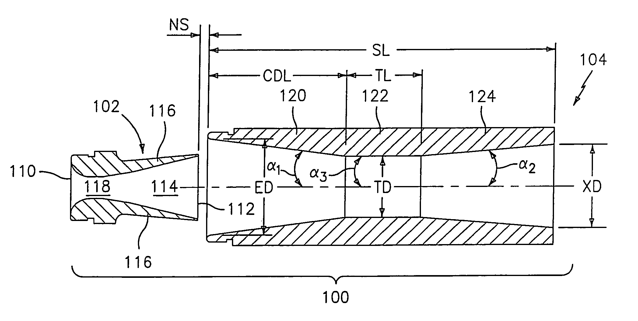
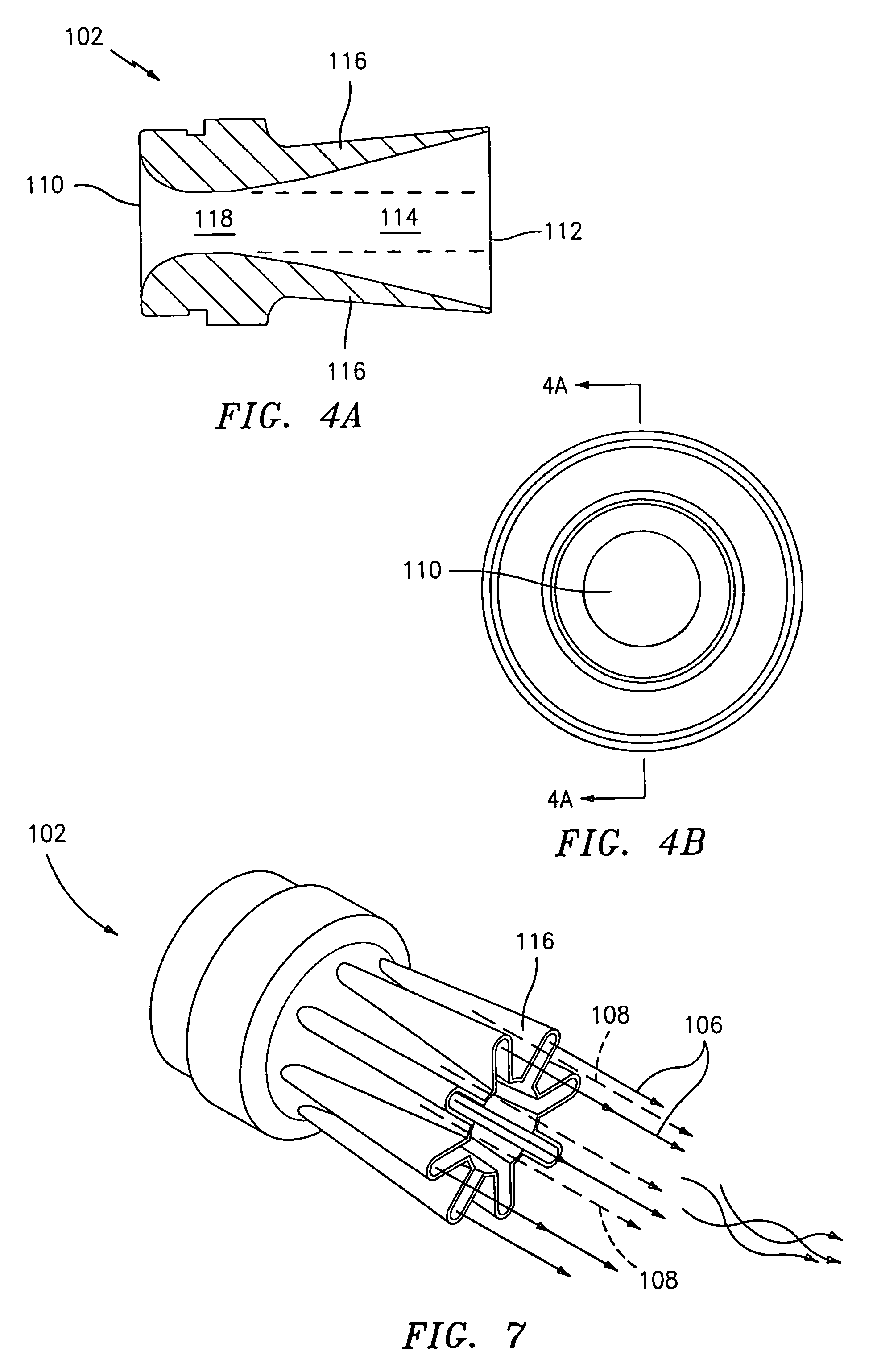
In operation, a primary flow of high-pressure steam or air is directed through the lobed primary nozzle, where it is choked and accelerated to supersonic speed. The primary flow then exits the lobed primary nozzle, where it entrains, or drags along, the secondary flow entering through the annular opening or space. As it does so, the lobed primary nozzle rapidly and thoroughly mixes the primary and secondary flows, which pass into the ejector shroud. The ejector shroud subsequently decelerates the combined flow while increasing the flow pressure, which increases suction performance and reduces energy loss. Because the lobed primary nozzle mixes the primary and secondary flows, an inner shroud wall boundary layer is energized, and any ejector shroud diffuser thereby can have steeper inner wall angles and is able to have the significantly smaller length-to-entrance-diameter ratio. The shorter length further enhances suction performance because of reduced wall friction effects. A low pressure or vacuum region is created upstream of the secondary flow by virtue of the primary flow entraining the secondary flow.

Problems solved by technology

The problem with steam ejector systems is that they are very expensive to fabricate and operate.
This results in significant material and manufacturing costs.
Moreover, the high-pressure steam jet required to produce the vacuum results in high operational costs.
These problems are compounded where multiple steam ejector systems are put in series to increase vacuum capability.

Method used


Image

  • Lobed convergent/divergent supersonic nozzle ejector system
  • Lobed convergent/divergent supersonic nozzle ejector system
  • Lobed convergent/divergent supersonic nozzle ejector system

Examples


Embodiment Construction

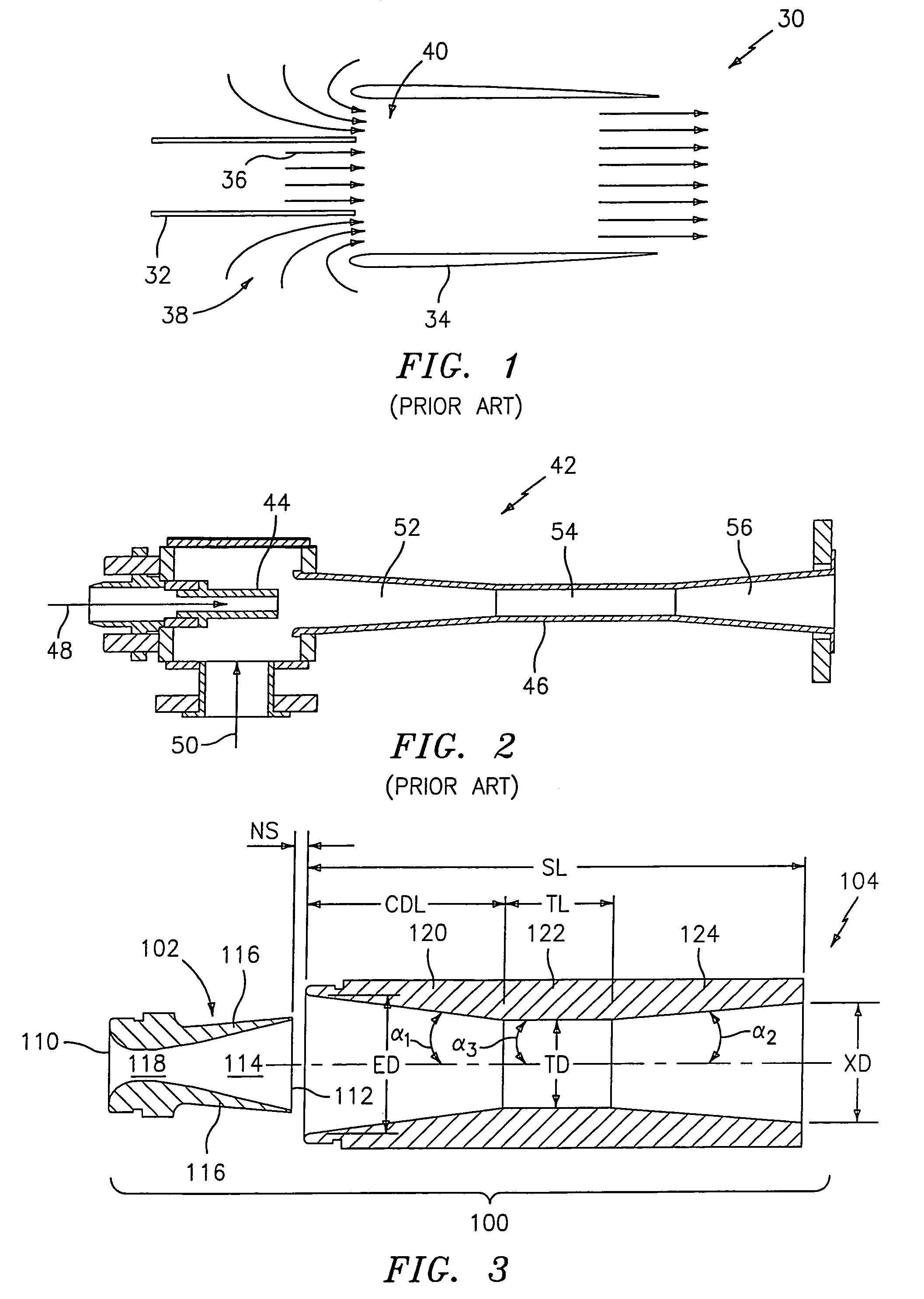
Turning now to FIGS. 3–10, various embodiments of a lobed, convergent / divergent, supersonic nozzle steam ejector or vacuum system 100 (hereinafter, “ejector system”), according to the present invention, will now be described. In a preferred embodiment, with reference to FIG. 3, the ejector system 100 comprises a lobed, supersonic primary nozzle 102 and a “shortened” convergent / divergent ejector shroud or diffuser 104 (by “shortened,” as discussed further below, it is meant that the shroud has a shroud-length-to-entrance-diameter (“SLED”) ratio significantly smaller than typical shrouds / diffusers, e.g., about 3.5 as compared to 10). The lobed nozzle 102 is positioned just upstream from the ejector shroud 104. In operation, a primary flow 106 of high-pressure steam or air is directed through the nozzle 102 and into the ejector shroud 104. The primary flow 106 entrains, or drags along, a secondary flow 108 as it enters the shroud. As it does so, the lobed nozzle 102 rapidly mixes the p...


PUM


Abstract

An ejector system comprises a lobed, supersonic primary nozzle and a convergent / divergent ejector shroud. The lobed nozzle is just upstream from the ejector shroud, such that there is an annular space between the nozzle and shroud for admitting a secondary flow. In operation, a primary flow of high-pressure steam or air is directed through the primary nozzle, where it is accelerated to supersonic speed. The primary flow then exits the primary nozzle, where it entrains and is mixed with the secondary flow, creating a low pressure region or vacuum. The ejector shroud subsequently decelerates the combined flow while increasing the flow pressure, which increases suction performance and reduces energy loss. Because the primary nozzle mixes the two flows, the ejector shroud is able to have a length-to-entrance-diameter ratio significantly smaller than typical shrouds / diffusers, which decreases the system's size and increases performance.

Description

FIELD OF THE INVENTIONThe present invention relates to steam / air ejectors and ejector vacuum systems.BACKGROUNDMany testing and manufacturing processes require vacuum or low-pressure environments. Some of these include jet engine simulations, salt water distillation, food processing, and many chemical reactions. Steam ejectors are often used to create this low-pressure region, and can vary in size from a 0.5 in. (12.7 mm) ejector for use with fuel cells to a 40 ft. (12 m) ejector for use in metal oxidation.An ejector is a fluid dynamic pump with no moving parts. As shown in FIG. 1 (labeled as “Prior Art”), a typical ejector 30 comprises a primary nozzle 32 and a mixing duct 34 downstream from (and generally axially aligned with) the primary nozzle 32. The ejector 30 uses a high velocity core flow 36, typically air or steam, to entrain a secondary, ambient flow 38, which can be a gas, liquid, or liquid / solid mix. In operation, the high velocity core 36, moving in the direction indica...

Claims


Application Information

Patent Timeline
Patent Type & Authority Patents(United States)
IPC IPC(8): F04F5/46F04F5/00
CPCF04F5/46
Inventor PRESZ, JR., WALTER M.WERLE, MICHAEL J.
Owner FLODESIGN WIND TURBINE
Why Eureka
Try Eureka