Split vent pin for injection molding

Inactive Publication Date: 2005-04-12
ACUSHNET CO
View PDF25 Cites 55 Cited by
  • Summary
  • Abstract
  • Description
  • Claims
  • Application Information

AI Technical Summary

Benefits of technology

One advantage of the present invention is that it may provide greater control and capacity of the evacuation of air and gasses in an injection mold cavity even when the injected material is molded with a high injection speed.
One embodiment of the present invention is a vent pin made of a plurality of pin sections with faces that join to define at least one primary vent along the inside of the tip of the vent pin. In another embodiment, the faces of the vent pin sections have a plurality of apertures on the portion of the vent pin facing inside the mold cavity. In yet another embodiment, the pin sections further include a secondary vent in fluid communication with the primary vent. In a preferred embodiment, the secondary vent is located inside the vent pin, although in another embodiment the secondary vent is located on the outer surface of the vent pin.
In another embodiment, the tip of the vent pin is shaped to form a plurality of dimples in the cover of a golf ball. In a preferred embodiment, the vent pin is shaped to include four protrusions for forming dimples on the object, while in another embodiment the vent pin has six protrusions. In yet another embodiment, the primary vent is formed by a channel cutout in one pin section joined with a second pin section having an essentially planar face.
Another embodiment of the p

Problems solved by technology

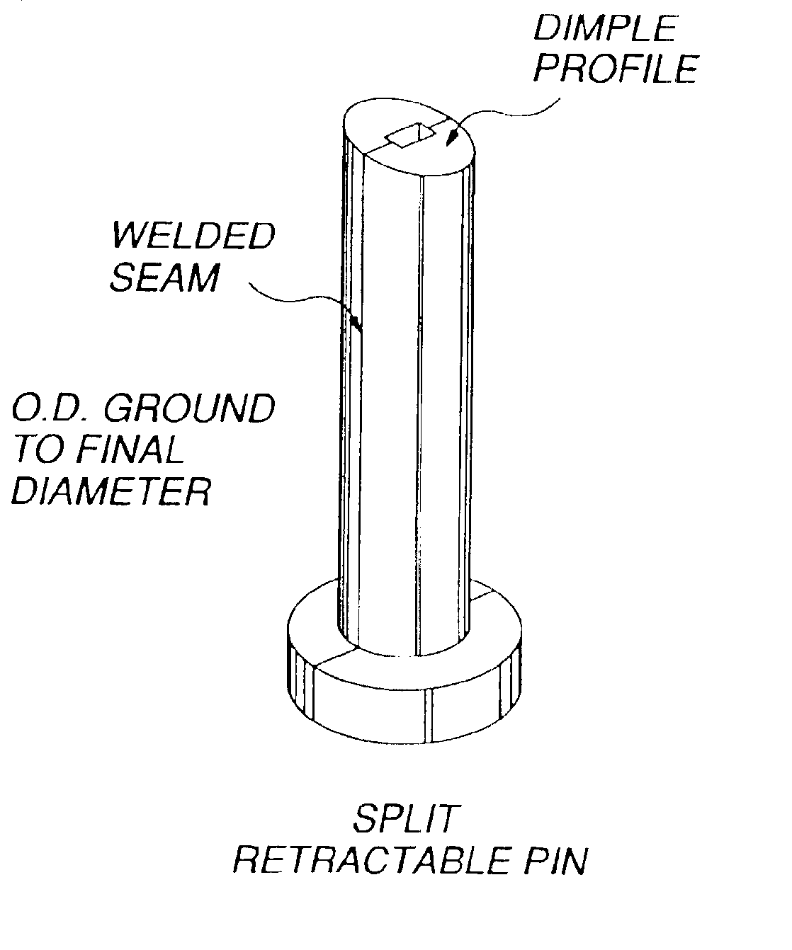
In particular, retractable pins do not have flats on the portion of the pin facing the equator of the ball, nor do they utilize a porous metal tip because doing so may cause the pins to bend or spread, thereby adversely affecting the ability of the retractable pins to accurately and securely position the ball core in the mold cavity during the injection process.
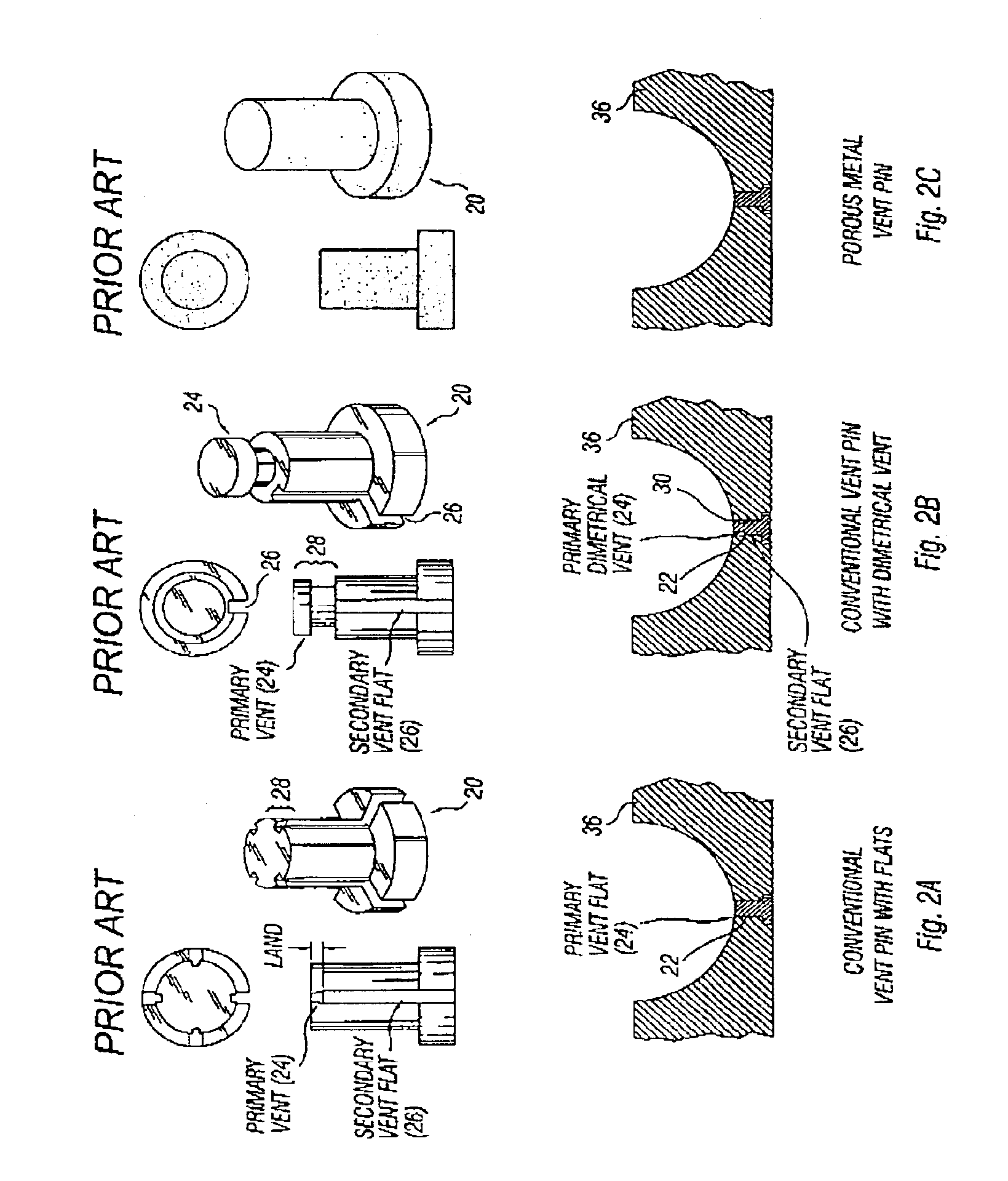
Despite that conventional vent pins are configured with primary and secondary vents or porous tips to increase ventilation capacity, ventilation of trapped air and gasses inside the mold often remains a limiting factor in the speed at which material is injected into the mold cavity.
If the vent holes are too small, poor ventilation can cause improper or inadequate venting of trapped air and gasses from the mold cavity during injection, which can have a deleterious effect on both the visual quality and durability of the newly formed layer.
If the injection speed of the material is too fast, the speed of evacuating air and gasses out of the mold cavity during the injection process can cause the newly formed layer to scorch or not completely fill the mold cavity.
Conversely, if the vent holes are too large, the injected material flows thereinto and forms flash on the newly formed layer, thereby requiring substantial additional processing for removal of the flash and surface finishing.
While lengthening the tim

Method used


Image

  • Split vent pin for injection molding
  • Split vent pin for injection molding
  • Split vent pin for injection molding

Examples


Embodiment Construction

FIGS. 2A-C illustrate how ventilation of air and gasses from an injection mold cavity has been achieved by utilizing solid vent pins that are relieved on the side or by using porous material to form the vent pin. As described above, these conventional configurations present limitations in ventilation capacity and may also require increased maintenance.

Under the present invention, the pin sections 44 may be constructed from two solid pins having typical geometry for a golf ball injection mold as illustrated in FIGS. 2A and 2B. Material from the first solid pin is removed longitudinally leaving a remaining piece that is approximately half cylindrical in cross section. The second pin is machined in a similar manner so that when the two sections are joined along their respective faces 46 and 48 they form a pin having outer dimensions approximating the dimensions of a solid pin.

After forming the pin section, a primary vent is constructed on its interior face 46 near the tip of pin. In on...


PUM


Abstract

The present invention is directed to an apparatus and method for venting trapped air and gasses in a mold. The mold and method comprise or use at least one pin formed from multiple pin sections. When assembled, the pin sections provide space on the interior of the pin through which trapped air and gasses can escape from the mold. The present invention may also be used to assist in ejecting an object from the mold. The pins can have circular or non-circular cross-sections and also may have dimple-forming projections to conform to a golf ball dimple pattern.

Description

FIELD OF INVENTIONThe present invention relates to venting methods and an apparatus for use in golf ball injection molding systems. In particular, the present invention provides greater capacity for releasing trapped air and gasses from a mold cavity during the injection molding process and for injecting air back into the cavity to assist in ejecting the ball upon completion of the molding process.BACKGROUND OF THE INVENTIONThe conventional method of forming an intermediate layer or cover layer of a golf ball utilizes an injection mold having two mold plates with hemispherical cavities that mate to form a spherical mold cavity when the mold halves are joined. At the initial stage of the injection molding process, a golf ball core is supported centrally within the mold cavity by a plurality of retractable pins near the upper and lower poles of the mold cavity so as to leave a space around the core for forming an intermediate layer or cover layer. A thermoplastic or thermosetting mate...

Claims


Application Information

Patent Timeline
IPC IPC(8): B29C45/14B29C45/34
CPCB29C45/14819B29C45/34Y10S425/812B29L2031/545
Inventor PUNIELLO, PAUL A.WILSON, ROBERT A.
Owner ACUSHNET CO
Why Eureka
Try Eureka