Eureka AIR delivers breakthrough ideas for toughest innovation challenges, trusted by R&D personnel around the world.

Cassette for electrophoretic gels

a gel and electrophoretic technology, applied in the field of cassettes, can solve the problems of affecting showing an increased tendency to break away from the remainder of the gel, and poorly defined wells, and achieve the effect of maintaining the integrity of the well

Inactive Publication Date: 2005-04-12
DYCENT BIOTECH SHANGHAI CO LTD
View PDF2 Cites 7 Cited by
  • Summary
  • Abstract
  • Description
  • Claims
  • Application Information

AI Technical Summary

Benefits of technology

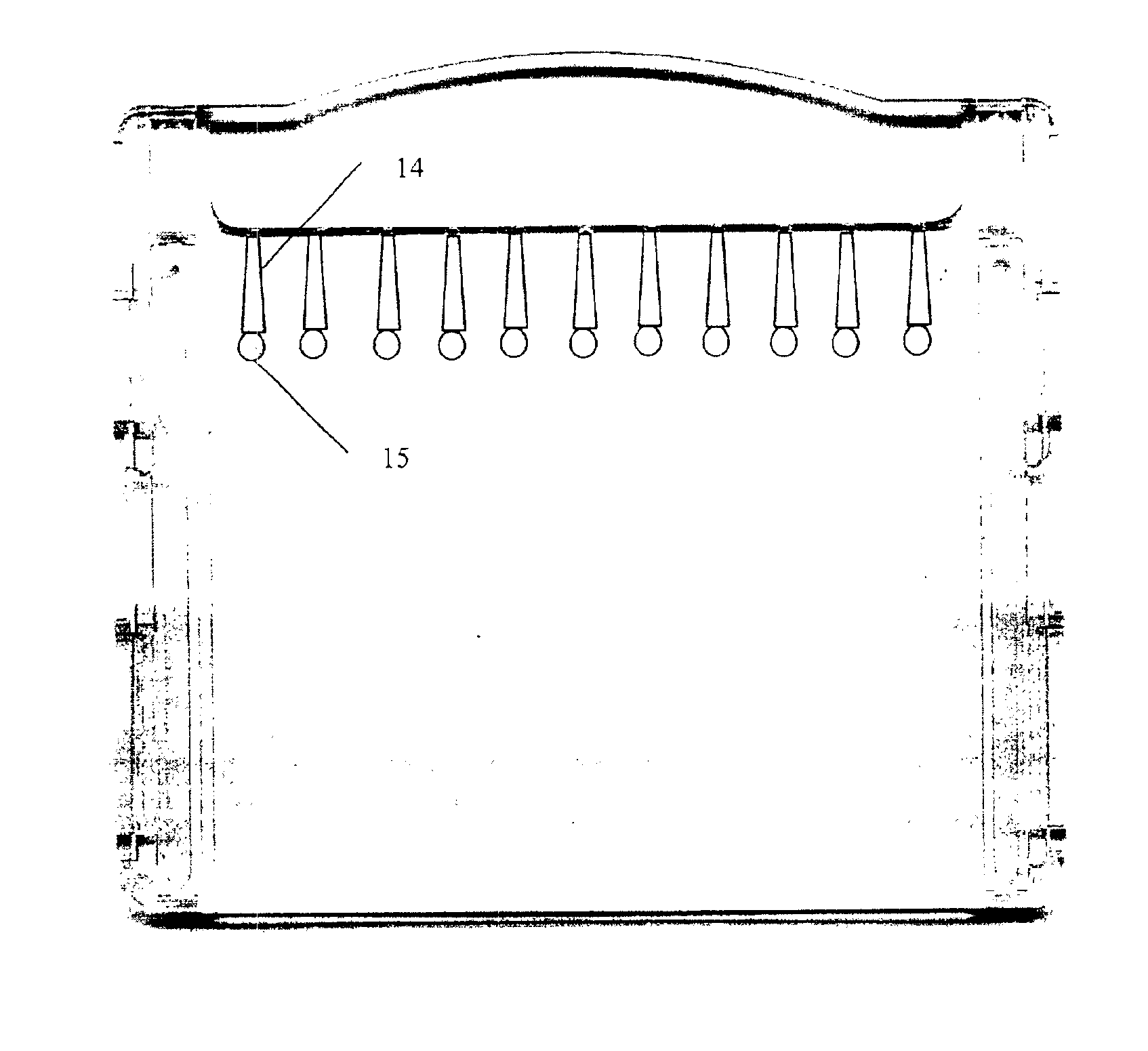
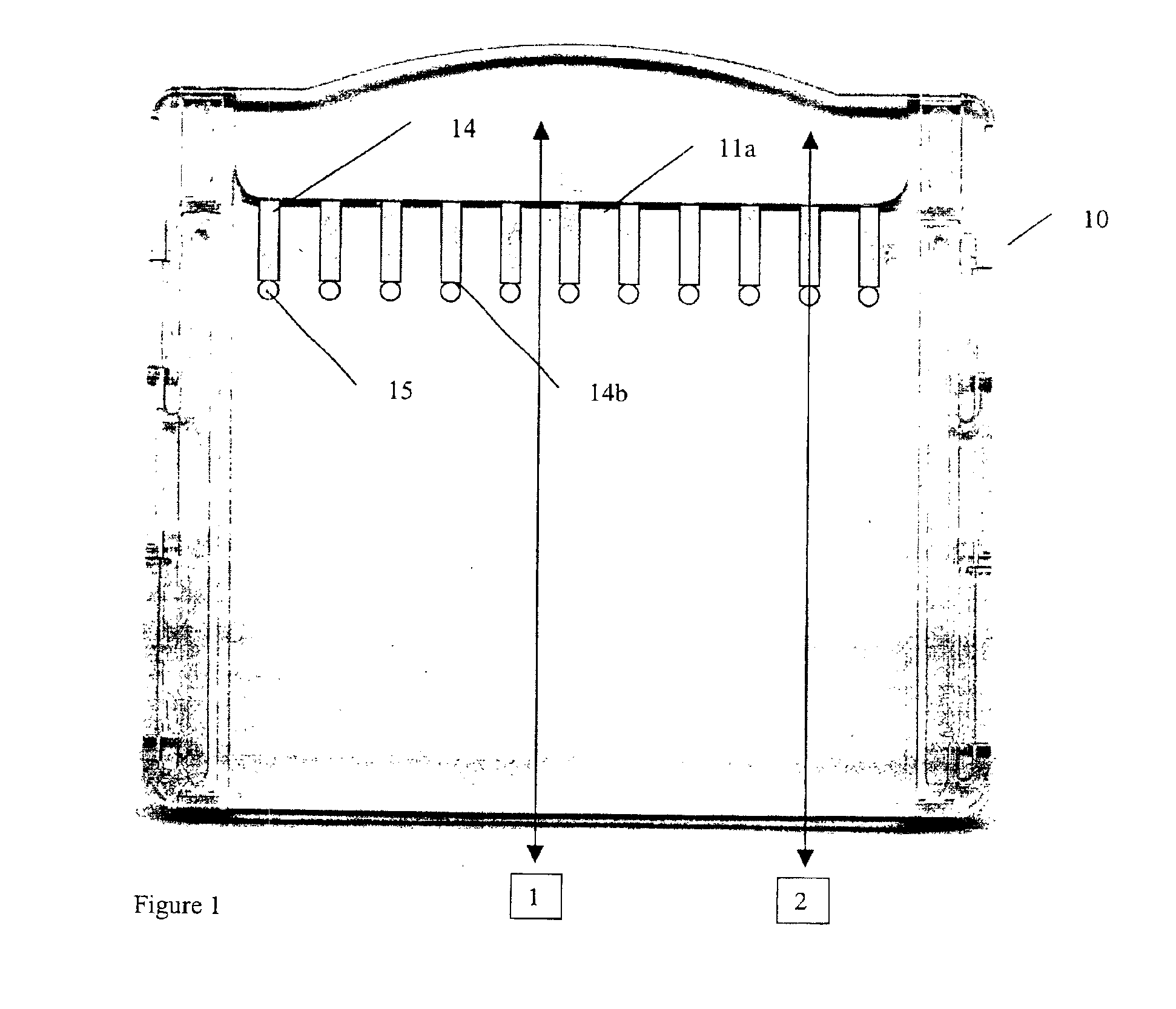
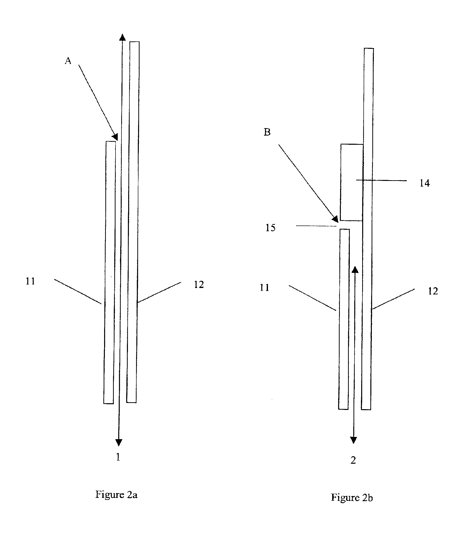
"The present invention provides an improved cassette for use in the formation of an electrophoretic gel. The cassette has solid dividing walls that are more resilient than traditional gel cassettes, and a plurality of holes at the base of the ribs to allow sufficient current flow. The size of the gap between the sample bands can be controlled by varying the size of the hole in the wall. The cassette also has a high concentration of acrylamide at the upper part of the gel, which allows for the separation of high molecular weight proteins. The invention also provides an improved cassette where the lower part of the well wall is formed from a finger of gel, which allows for the re-establishment of parallel current flow through the gel before the well base is reached by the current."

Problems solved by technology

However, this arrangement has a disadvantage that upon withdrawal of the comb the fingers of the gel may, with time, show an increased tendency to break away from the remainder of the gel.
This results in poorly defined wells.
This has resulted that the tongues may fall over side ways occluding an adjacent well.
Whilst this arrangement provides stable wells suitable to hold the sample material, this arrangement has a disadvantage that the solid walls of the wells interfere with the smooth flow of electric current through the electrophoretic gel: because of the ribs, the current is initially confined and then spreads out which has a result that as the run proceeds bands from adjoining wells tend to spread out and merge with one another.
However, the disadvantage of the cassette shown in WO 97 / 04307 is that as the combs are withdrawn, the tops of the gel fingers tend to break away from the remainder of the gel finger.

Method used


Image

  • Cassette for electrophoretic gels
  • Cassette for electrophoretic gels
  • Cassette for electrophoretic gels

Examples


Embodiment Construction

Referring to the drawings FIG. 1 shows a first electrophoresis cassette 10 which may be formed in two parts by injection moulding or by other methods from a suitable synthetic plastic material.

One part forms a first side wall 11 of the cassette which is banded on each side by a connecting means comprising a pair of spaced apart ridges not shown.

The other part forms a second side wall 12 of the cassette which is also banded on each side by a pair of spaced ridges, not shown. The ridges interdigitate to form a seal along each side of the cassette to prevent leakage therethrough of the gel forming liquid during setting of the gel or flow of an electrical current during electrophoresis.

The ridges are of a sufficient thickness that a gel receiving space 13 is defined between the side walls which lie in substantially parallel planes. Such a construction as described above is already well known in the prior art see, for example, WO 97 / 04307 the contents of which are incorporated herein by ...


PUM

PropertyMeasurementUnit
diameteraaaaaaaaaa
diameteraaaaaaaaaa
sizeaaaaaaaaaa

Abstract

An improved cassette for use in the formation of an electrophoretic gel comprises two plates with substantially planar walls having two sides and two ends so arranged in a side by side spaced apart array to form a gel receiving space between them. A plurality of dividing ribs on one or each of the walls extend from a first end of the wall or walls substantially parallel to at least one of the sides thereof to a rib base end. The ribs extend into the space so as to subdivide at least one end of the space into a plurality of substantially parallel wells. A plurality of holes extend through at least one of the walls of the cassette located at or adjacent the base of the dividing rib and aligned with the rib. The arrangement of holes allow sufficient current flow to replace that lost due to the dividing ribs. The structure retains the advantage of having solid dividing walls which are considerably more resilient than dividing walls made from fingers of gel even when reinforced with pegs or projections and yet by virtue of the provision of a hole at the base of the ribs allows sufficient current flow at the base of each rib that the current flow through the space is substantially uniform, thus preventing spreading of the bands as they form in the body of the gel.

Description

FIELD OF THE INVENTIONThe present invention relates to a cassette for use in the formation of an electrophoretic gel and more particularly to such a cassette which includes means to assist in separating and defining individual sample receiving wells at one end of the electrophoretic gel.BACKGROUND ARTElectrophoretic gels, usually comprising hydrogels such as agarose or polyacrylamide are used for the separation of nucleic acids, proteins and other macromolecular compounds. The sample to be separated is placed at one end of the gel and a direct electric field is applied between the ends of the gel causing the components of the sample to migrate through the gel at rates dependent upon their molecular size and charge.A mixture of components to be separated is normally introduced into one of a number of small wells formed in an upper edge of the gel before the electric current is applied. It is usual to run a number of such mixtures simultaneously on an electrophoretic gel in a side by ...

Claims


Application Information

Patent Timeline
Patent Type & Authority Patents(United States)
IPC IPC(8): G01N27/447
CPCG01N27/44743G01N27/44704
Inventor MANUSU, HOWARD PERICLESATCHISON, SHAUN
Owner DYCENT BIOTECH SHANGHAI CO LTD
Why Eureka
Eureka Blog
Learn More