
Apparatus for the precise location of reaction plates

a technology for reaction plates and apparatuses, which is applied in the direction of material analysis, laboratory glassware, instruments, etc., can solve the problems that the prior plate-alignment techniques that rely on the outer side edges or sidewalls of the plate to position the wells are inherently unreliabl

Inactive Publication Date: 2005-04-12
APPL BIOSYSTEMS INC
View PDF44 Cites 31 Cited by
  • Summary
  • Abstract
  • Description
  • Claims
  • Application Information

AI Technical Summary

Benefits of technology

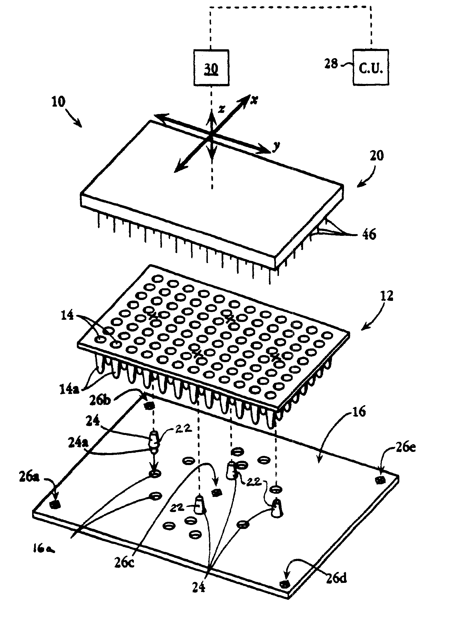
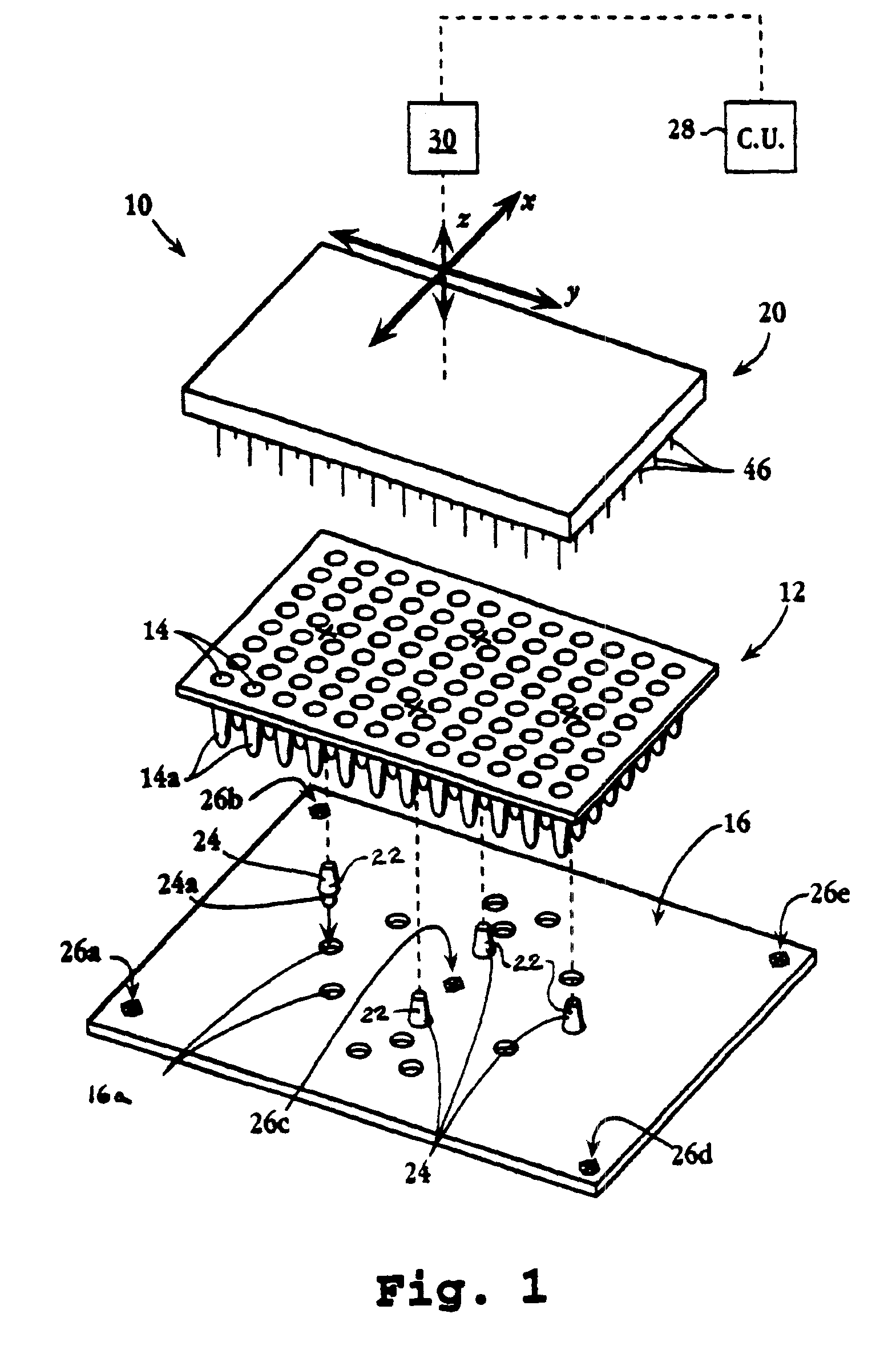
In another of its aspects, the present invention provides an improvement for a microplate apparatus having (i) a microtiter plate defining an array of sample wells, each having interior wall surfaces, (ii) a plate-handling machine having a plate-support region, e.g., a surface, and an acting-member support with one or more sample-handling or reading members disposed therealong, each member being adapted to operate on an individual well in the plate, and (iii) a control unit for controlling the position of the support with respect to defined coordinates on the plate-support surface. An improved plate locating and aligning arrangement is provided, including locator structure depending from the acting-member support for engaging the interior wall surfaces of one or more wells, when introduced therein, so as to fix the position of one or more of the other wells in alignment with the sample-handling or reading member(s).

Problems solved by technology

As discussed above, prior plate-alignment techniques that rely on the outer side edges or sidewalls of a plate to position the wells are inherently unreliable, as the spatial relation between such plate structures and the various wells differ markedly from plate to plate.

Method used


Image

  • Apparatus for the precise location of reaction plates
  • Apparatus for the precise location of reaction plates
  • Apparatus for the precise location of reaction plates

Examples


Embodiment Construction

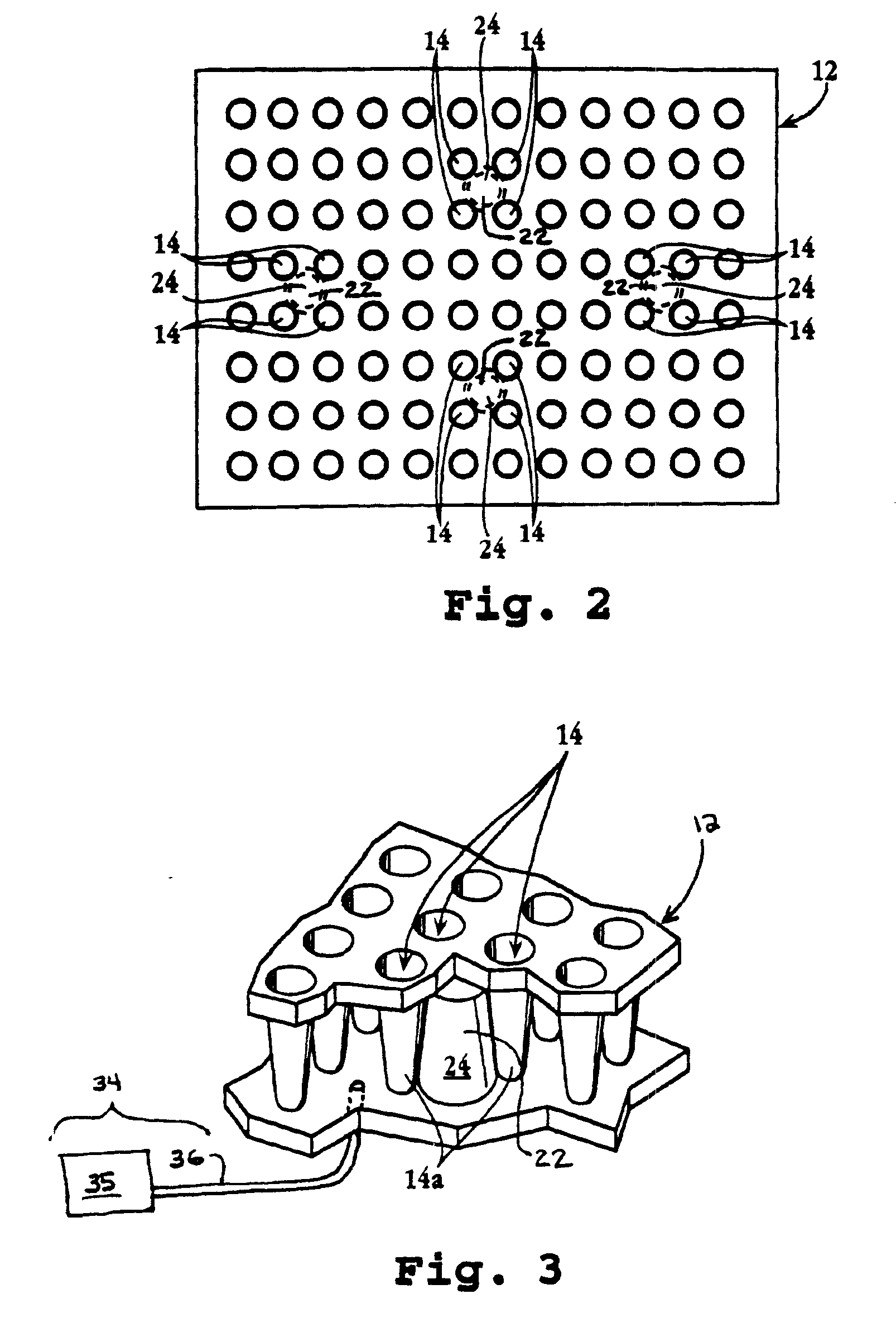
The present invention provides an apparatus and method for accurately locating a multi-well plate at a plate-support location, e.g., a work surface or deck, of an automated laboratory machine, such that one or more acting members, such as an array of pipette tips, optical sensors, or other members, can operate on the individual wells. Features of interest of the plate, such as one or more wells, are used as the primary locating structures of the plate for aligning the entire array of wells with respect to the machine. In preferred embodiments, for example, the interior and / or exterior surface regions of one or more wells of a multi-well plate can be engaged by locating structure of a machine.

An exemplary microplate apparatus, indicated generally by the reference numeral 10, is depicted in FIG. 1. In overview, apparatus 10 includes a plate (also referred to as a tray), denoted as 12, defining an array of sample wells, such as 14, each having exterior wall surfaces 14a. A plate-handli...


PUM


Abstract

Generally, the present invention provides a device and method for accurately locating a multi-well plate at a plate-support location, e.g., a work surface, of an automated laboratory machine, such that one or more acting members of the machine, such as an array of pipette tips, optical sensors, or the like, can accurately address and operate on the individual wells. Interior and / or exterior surface regions of one or more wells of a multi-well plate are used as the primary plate features engaged by locating structure of the machine. In one particular embodiment one or more upwardly tapered projections extend from a plate-support surface of a plate-handling machine for mating engagement with the exterior surface regions of one or more wells. In another embodiment, the exterior surface regions along one or more well bottoms are engagingly received within bores, or other receiving structure, formed on the place-support surface of a machine. In a further embodiment, one or more downwardly extending projections depend from an acting-member support, along with the acting members of a machine. Introduction of the projections into some of the wells of a multi-well plate serves to align the acting members with the plate's other wells.

Description

FIELD OF THE INVENTIONThe present invention relates to the positioning of multi-well plates in laboratory machines. More particularly, the invention provides an apparatus and method for accurately locating a multi-well plate at a plate-support region of a laboratory machine, so that one or more acting members, e.g., an array of pipette tips or optical readers, can operate on the individual wells.BACKGROUND OF THE INVENTIONIn chemical and biological laboratories, it is often necessary to perform analytical and / or experimental assays or procedures on large numbers of laboratory specimens. For example, a lab technician might need to determine the reaction of many different specimens against one or more reagents, such as labeled probes. Common tasks that are performed for each sample include reagent transfers (e.g., aspiration and dispensing), mixing and stirring, as well as reading the results of each assay.Typically, in years past, each sample was processed in its own, separate contai...

Claims


Application Information

Patent Timeline
IPC IPC(8): B01L3/00G01N35/10B01J19/00G01N35/02B01L3/02C40B20/02C40B60/10
CPCB01L3/5085G01N35/1065Y10T436/2575Y10T436/114165Y10T436/11Y10T436/113332
Inventor KOWALLIS, REID BURTONCOX, DAVID M.
Owner APPL BIOSYSTEMS INC
Learn More