Insertion-type liquid metal latching relay array

a relay array and liquid metal technology, applied in relays, generators/motors, snap-action arrangements, etc., can solve the problems of liquid connection between fixed and moving contact pads that can be broken, and achieve the effect of high frequency capability and amenability to manufactur

Inactive Publication Date: 2005-04-12
AGILENT TECH INC
View PDF95 Cites 3 Cited by
  • Summary
  • Abstract
  • Description
  • Claims
  • Application Information

AI Technical Summary

Benefits of technology

A high frequency electrical relay array is disclosed that uses a conducting liquid in the switching mechanism. Each relay element in the relay array uses an actuator, such as a piezoelectric element, to cause the switch actuator to insert into a cavity in a static switch contact structure. The cavity has sides and a pad on its end that are wettable by the conducting liquid. The cavity is filled with the conducting liquid, which may be liquid metal. Insertion of the switch actuator into the cavity causes the conducting liquid to be displaced outward and come in contact with the contact pad on the switch actuator. The volume of conducting liquid is chosen so that when the actuator returns to its rest position, the electrical contact is maintained by surface tension and by wetting of the contact pads on both the static switch contact structure

Problems solved by technology

When the switch actuator retracts away from the static switch contact structure, the available volume for conducting liquid inside the fixed switch contact structure increases and the combination of the movement of the conducting liquid into the cavity and the contact pad on the switch actuator moving away fro

Method used


Image

  • Insertion-type liquid metal latching relay array
  • Insertion-type liquid metal latching relay array
  • Insertion-type liquid metal latching relay array

Examples


Embodiment Construction

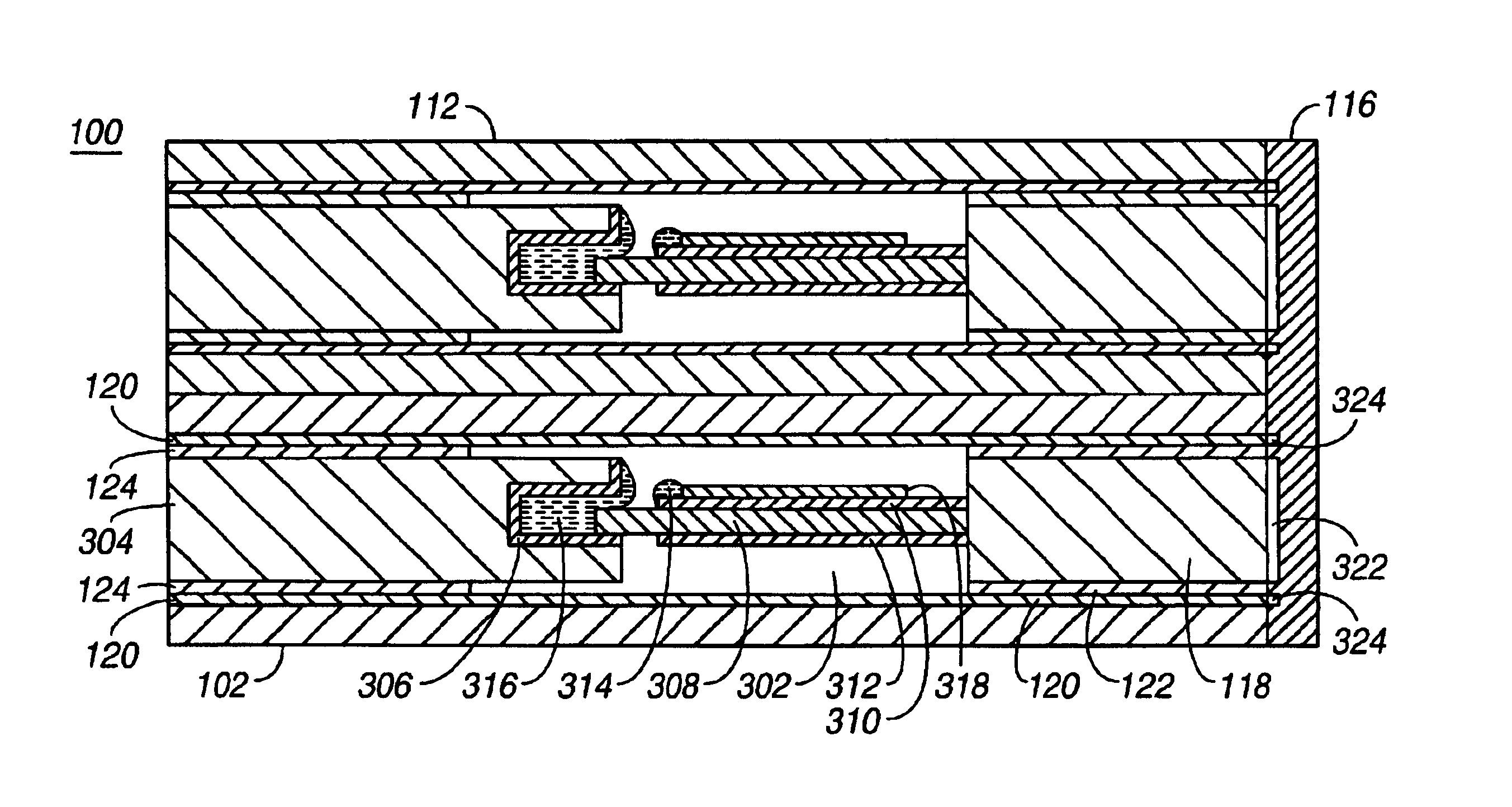
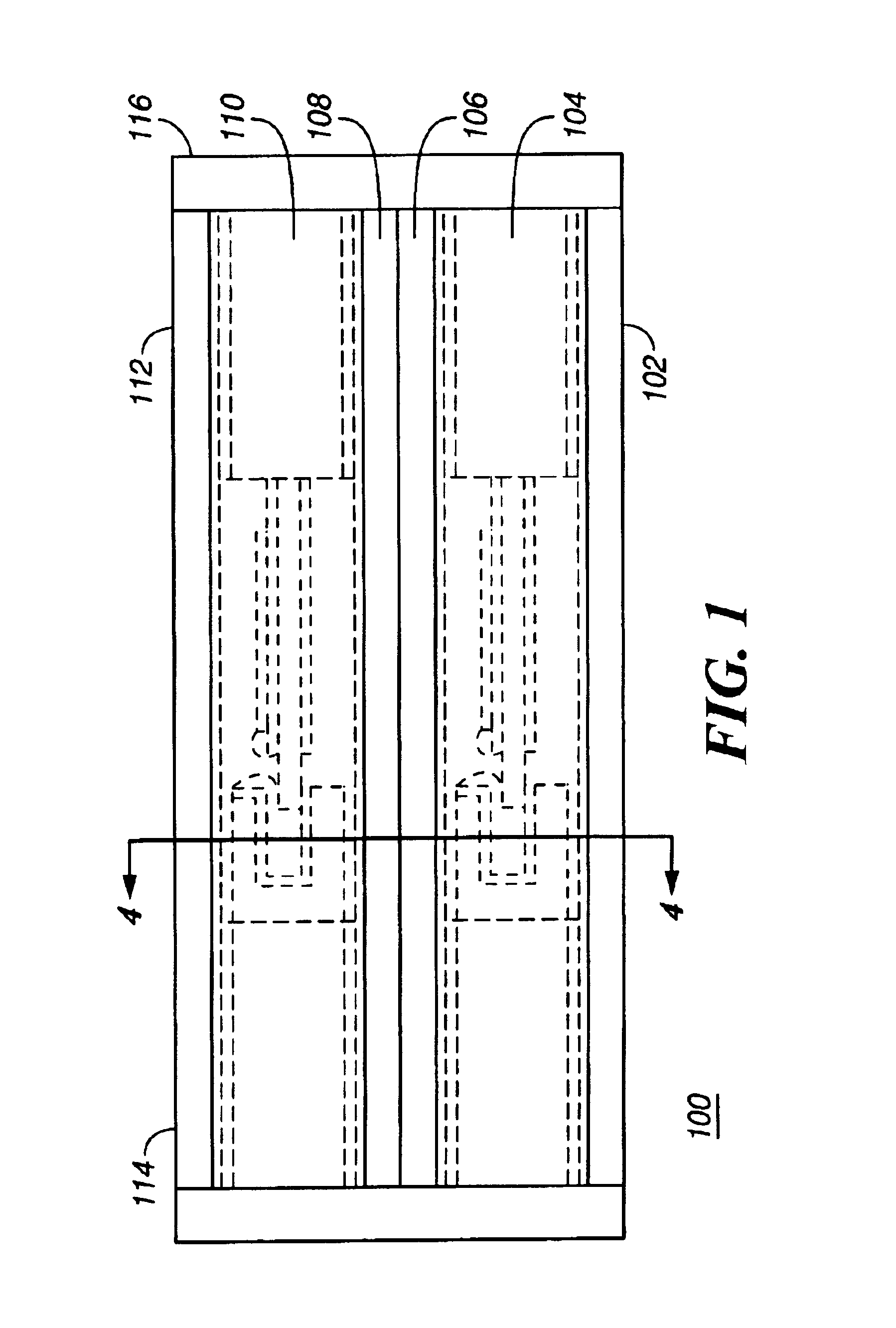
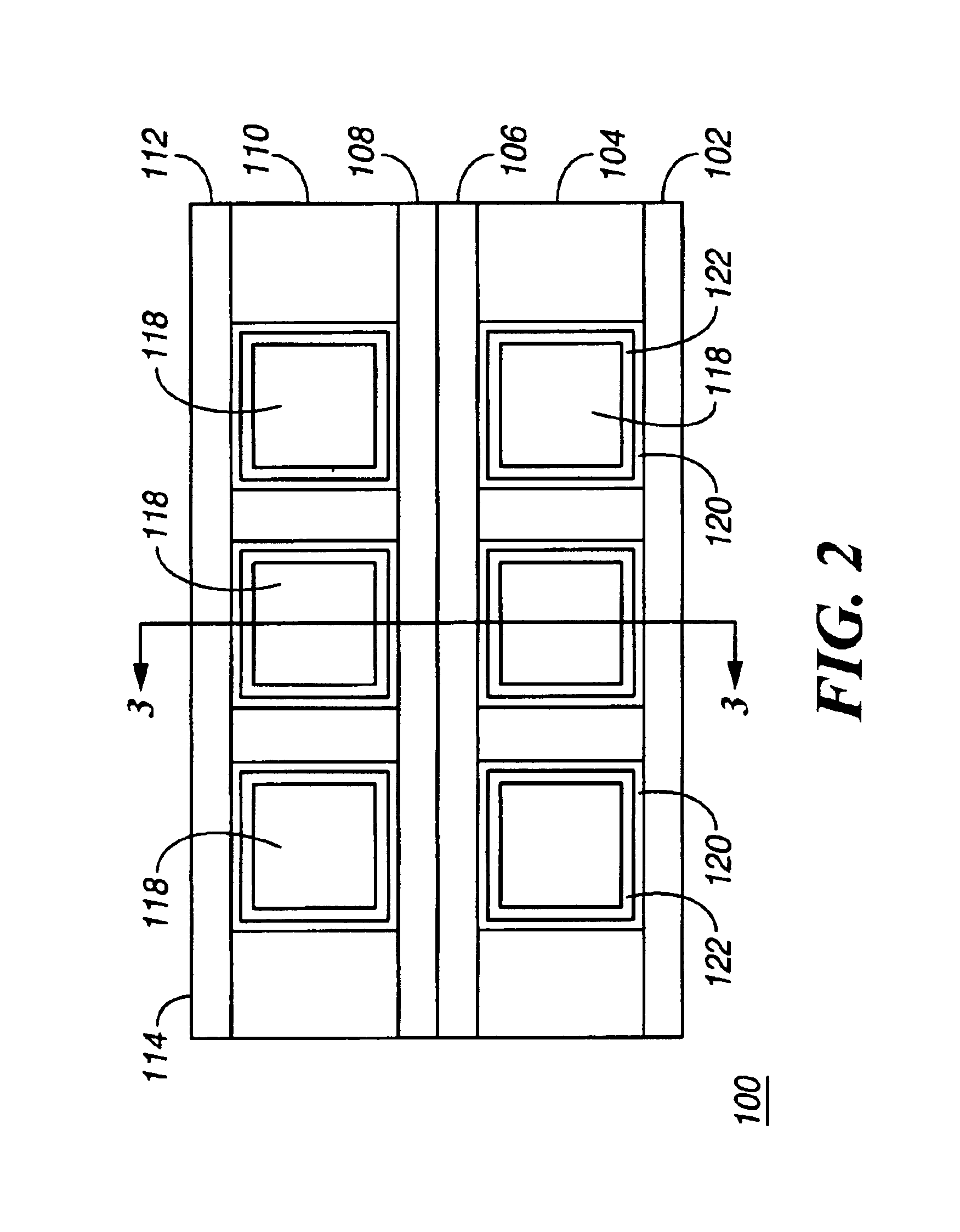
While this invention is susceptible of embodiment in many different forms, there is shown in the drawings and will herein be described in detail one or more specific embodiments, with the understanding that the present disclosure is to be considered as exemplary of the principles of the invention and not intended to limit the invention to the specific embodiments shown and described. In the description below, like reference numerals are used to describe the same, similar or corresponding parts in the several views of the drawings.

The relay array of the present invention incorporates a number of electrical switching elements or relays. Each relay uses a conducting liquid, such as liquid metal, to bridge the gap between two electrical contacts and thereby complete an electrical circuit between the contacts. Each relay uses an actuator, such as a piezoelectric element, to cause the switch actuator to insert into a cavity in a fixed switch contact structure. The cavity has sides and a p...


PUM


Abstract

An electrical relay array using conducting liquid in the switching mechanism. The relay array is amenable to manufacture by micro-machining techniques. Each element of the relay array uses an actuator, such as a piezoelectric element, to cause a switch actuator to insert into a cavity in a static switch contact structure. The cavity has sides and a pad on its end that are wettable by the conducting liquid. The cavity is filled with the conducting liquid, which may be liquid metal. Insertion of the switch actuator into the cavity causes the conducting liquid to be displaced outward and come in contact with the contact pad on the switch actuator. The volume of conducting liquid is chosen so that when the actuator returns to its rest position, the electrical contact is maintained by surface tension and by wetting of the contact pads on both the static switch contact structure and the actuator. When the switch actuator retracts away from the static switch contact structure, the available volume for conducting liquid inside the fixed switch contact structure increases and the combination of the movement of the conducting liquid into the cavity and the contact pad on the switch actuator moving away from the bulk of the conducting liquid causes the conducting liquid connection between the fixed and moving contact pads to be broken. When the switch actuator returns to its rest position, the contact remains electrically open because there is not enough conducting liquid to bridge the gap without being disturbed. The high frequency capability is provided by the additional conductors in the assembly, which act to make the switch a coaxial structure.

Description

FIELD OF THE INVENTIONThe invention relates to the field of micro-electromechanical systems (MEMS) for electrical switching, and in particular to a high frequency piezoelectrically actuated latching relay array with liquid metal contacts.BACKGROUND OF THE INVENTIONLiquid metals, such as mercury, have been used in electrical switches to provide an electrical path between two conductors. An example is a mercury thermostat switch, in which a bimetal strip coil reacts to temperature and alters the angle of an elongated cavity containing mercury. The mercury in the cavity forms a single droplet due to high surface tension. Gravity moves the mercury droplet to the end of the cavity containing electrical contacts or to the other end, depending upon the angle of the cavity. In a manual liquid metal switch, a permanent magnet is used to move a mercury droplet in a cavity.Liquid metal is also used in relays. A liquid metal droplet can be moved by a variety of techniques, including electrostat...

Claims


Application Information

Patent Timeline
IPC IPC(8): H01H29/00H01H29/18H01H67/22H01H57/00H01H67/00B81B5/00B81B7/04H01H1/08H01H55/00
CPCH01H29/18H01H57/00H01H2057/006H01H2001/0042H01H2029/008H01H67/22
Inventor WONG, MARVIN GLENNFONG, ARTHUR
Owner AGILENT TECH INC
Why Eureka
Try Eureka