
Compact and lightweight TEM-line network for RF components of antenna systems

a technology of temline network and antenna system, which is applied in the field of compact and lightweight temline network for rf (radiofrequency) components of antenna system, can solve the problems of limiting the power handling of signal power, large overall volume and mass, and preventing their use in many applications, etc., and achieves excellent assembly precision, low pim products, and easy manufacturing.

Active Publication Date: 2018-09-04
MACDONALD DETTWILER & ASSOC INC
View PDF1 Cites 0 Cited by
  • Summary
  • Abstract
  • Description
  • Claims
  • Application Information

AI Technical Summary

Benefits of technology

[0016]An advantage of the present invention is that the TEM-line network architecture includes a center or inner conductor that is supported only at electrical grounding locations, i.e. without the use of any dielectric supports.
[0017]A further advantage of the present invention is that the TEM-line network architecture is capable of low PIM products, especially because of the electrical connection between the inner conductor and the outer conductor or chassis.
[0018]Another advantage of the present invention is that the TEM-line network architecture is amenable to manufacturing with excellent assembly precision.
[0019]A further advantage of the present invention is that the TEM-line network architecture is capable of high thermal dissipation, especially because of a good thermal conduction path between the inner conductor and the outer conductor or chassis, and because of the absence of dielectric supports.
[0020]Still another advantage of the present invention is that the TEM-line network architecture is relatively immune to ESD (Electrostatic Discharge), again because of the electrical connection between the inner conductor and the outer conductor or chassis, and because of the absence of dielectric supports.
[0021]Yet another advantage of the present invention is that the TEM-line network architecture has a good structural strength, again because of a structural link between the inner conductor and the outer conductor or chassis.

Problems solved by technology

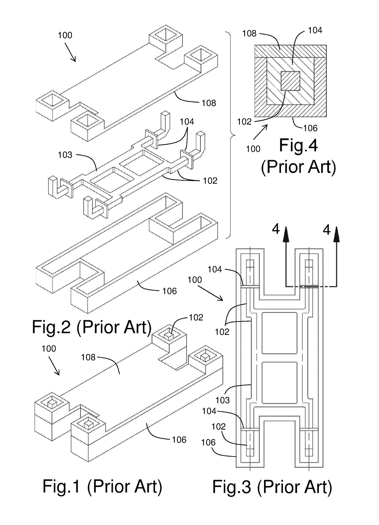
However, the typical relatively large overall volume and mass achieved with such antenna feed systems implementations, including an OMJ with waveguide network for both Tx and Rx signals paths, preclude their use in many applications, where the volume and the mass should still be reduced by at least a factor of two (2).
Effectively, the electrically isolating dielectric supports of the center conductor limit the signal power handling because of heat generation due to signal losses within the supports that need to be dissipated (in vacuum environment for space applications).
This in turn generally increases the overall insertion loss of the antenna system, and therefore decreases the performance of the antenna.

Method used


Image

  • Compact and lightweight TEM-line network for RF components of antenna systems
  • Compact and lightweight TEM-line network for RF components of antenna systems
  • Compact and lightweight TEM-line network for RF components of antenna systems

Examples


embodiment 10

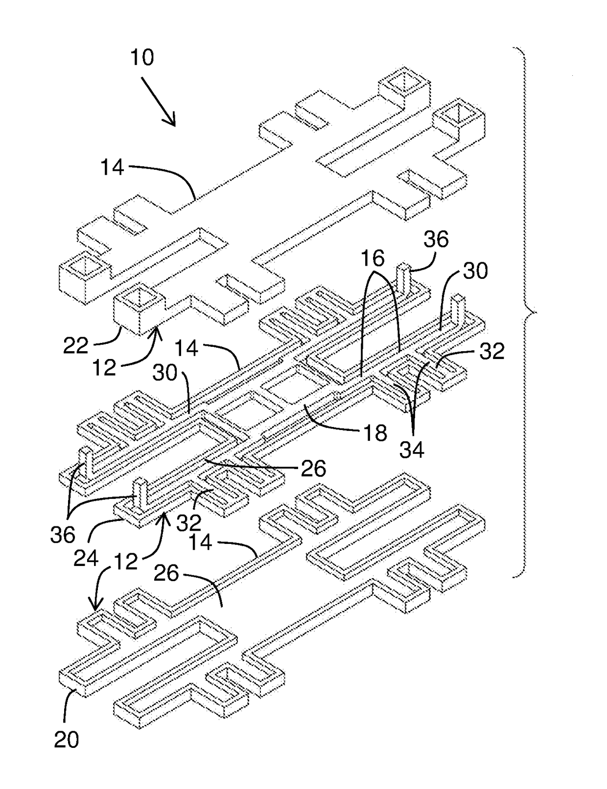
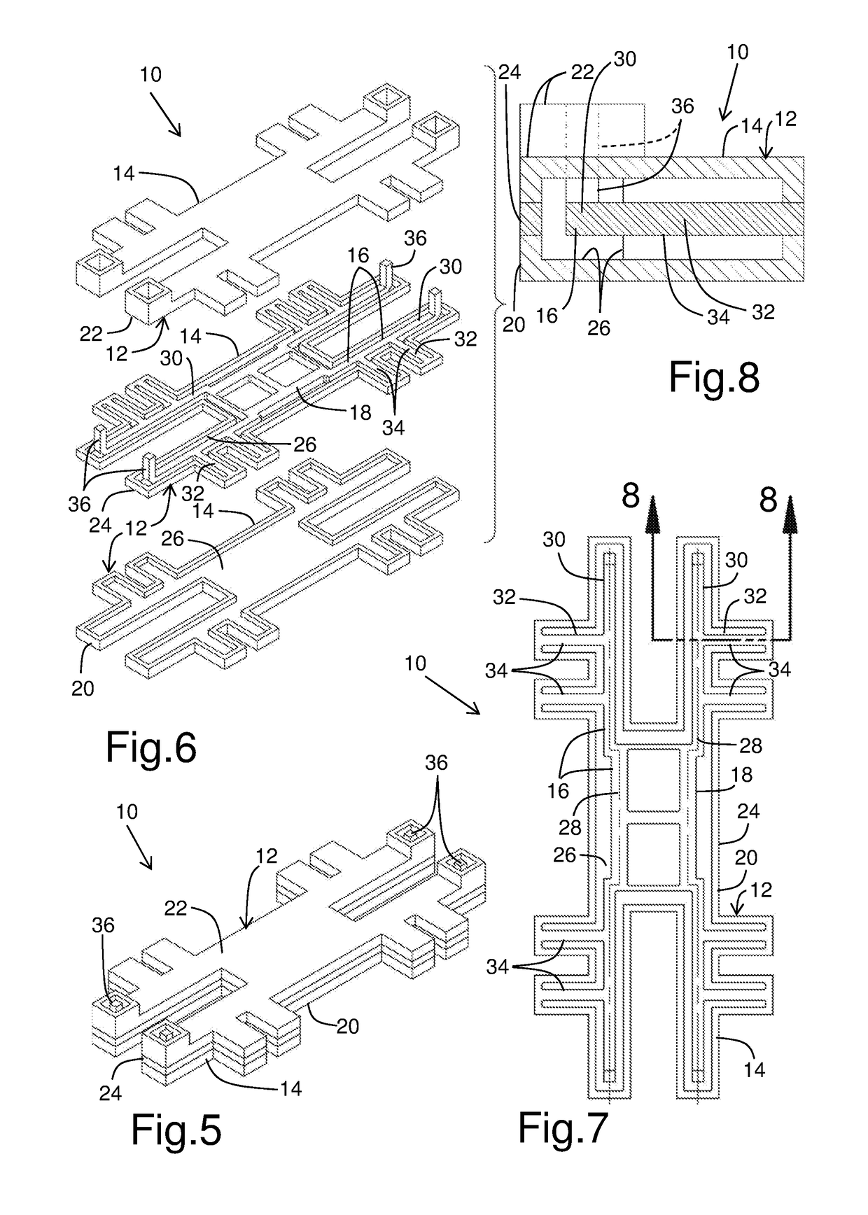
[0053]The TEM-line coupler 10 typically includes a main body 12 defining an outer conductor 14 forming a generally closed (in cross-section) channeled path having an inner or center conductor 16 typically electromagnetically isolated therefrom at RF (Radio-Frequency) frequencies but electrically DC (Direct Current) connected (grounded) thereto at predetermined locations, and running into and along the channeled path and supporting antenna electromagnetic signals running there along. The outer conductor 14 is typically formed out of three layers, namely a bottom layer 20, a top layer 22, and an intermediate layer 24 located in-between. The center conductor 16 is supported within the channeled path only at at least one, and typically all of the predetermined locations, with no dielectric supports at all. In the embodiment 10 shown, the center conductor 16 includes a 3-branch coupler 18 generally centrally located.

[0054]At least the inner surface 26 of the channel path is electrically ...

embodiment 40

[0059]Referring to FIGS. 9 and 10, there is shown a TEM-line network or portion of a dual-band antenna feed system 40 architecture in accordance with an embodiment of the present invention. The dual-band antenna feed system 40 operates with first and second signals having their respective frequency band, such as Tx and Rx signals. In the embodiment 40 shown in FIGS. 9 and 10, the feed system has a waveguide central common Tx / Rx port 42 connectable to a feed horn (not shown).

[0060]The dual-band antenna feed system 40 typically includes two (2) different network architectures for both the first (Tx) end second (Rx) signal paths. The Rx signal path is typically realized in waveguide technology capable of generating dual polarization signals, as dual LP (linear polarization) or dual CP (circular polarization) signals, such that it could include a circular or square waveguides feed network with septum polarizers or alternatively an OMJ based network with RF signal combiners and a coupler...


PUM


Abstract

A TEM-line network architecture for RF components used in antenna system, includes an electrically conductive main body forming an outer conductor defining a signal channel, and an electrically conductive center conductor electrically grounded to the main body at predetermined locations. The center conductor is electromagnetically isolated from the outer conductor at RF frequencies while being connected and supported within the signal channel only at at least one of the predetermined locations. The outer conductor is preferably formed of three layers with the center conductor being integral with one of the layers.

Description

CROSS REFERENCE TO RELATED APPLICATION[0001]This application claims priority of U.S. Provisional Application for Patent No. 62 / 288,283 filed Jan. 28, 2016, the content of which is incorporated herein by reference in its entirety.FIELD OF THE INVENTION[0002]The present invention relates to the field of antenna systems, and is more particularly concerned with a compact and lightweight TEM-line (Transverse Electromagnetic) network for RF (Radio-Frequency) components of antenna systems, such as dual-band antenna feed systems.BACKGROUND OF THE INVENTION[0003]It is well known in the art of transmission lines for electromagnetic signals in antennas to use feed systems implementing Orthogonal Mode Junction (OMJ) with waveguide networks for both Tx (transmit) and Rx (receive) signal paths. Such implementation, especially for on-board spacecraft applications, typically fulfils operation requirements such as:[0004]combined Tx and Rx functionality;[0005]dual circular or linear polarization func...

Claims


Application Information

Patent Timeline
Patent Type & Authority Patents(United States)
IPC IPC(8): H01P5/12H01P5/19H01P1/202H01P3/06H01P3/02
CPCH01P5/19H01P3/06H01P3/02H01P1/202
Inventor UHER, JAROSLAWLAMOUREUX, STEPHANERICHARD, SYLVAIN
Owner MACDONALD DETTWILER & ASSOC INC
Learn More