Sound beam loudspeaker system

a loudspeaker and beam technology, applied in the field of sound beam loudspeaker systems, can solve the problems of difficult arrangement of five to six loudspeakers in a room, the number of speakers, etc., and achieve the effect of maximum directivity of low frequency beams and low cos

Inactive Publication Date: 2006-09-14
1 LIMITED ST JOHN S INNOVATION CENT
View PDF34 Cites 139 Cited by
  • Summary
  • Abstract
  • Description
  • Claims
  • Application Information

AI Technical Summary

Benefits of technology

[0042] This arrangement allows less expensive high frequency transducers to form the bulk of the array and to output all the low frequency signals using a smaller set of low frequency or wideband transducers. These transducers are preferably at the perimeter of the array to enable maximum directivity of the low frequency beams.
[0043] In a particularly low cost variant, the array is preferably a line array having one, two or three horizontal lines. This allows beams to be directed in a horizontal plane with little directivity possible in a vertical direction.

Problems solved by technology

In ordinary homes, however, it is difficult to arrange five to six loudspeakers in a room.
As new surround sound systems are often incompatible with any existing stereo systems, a user is left with the choice of having two co-existing systems in one room (bringing the number of speakers up to seven or eight) or to discard the old system.
This being clearly unsatisfactory, attempts have been made in recent years to reduce the number of speakers to generate surround sound or to at least provide for a better integration between new surround sound systems and any legacy stereo equipment.

Method used


Image

  • Sound beam loudspeaker system
  • Sound beam loudspeaker system
  • Sound beam loudspeaker system

Examples


Embodiment Construction

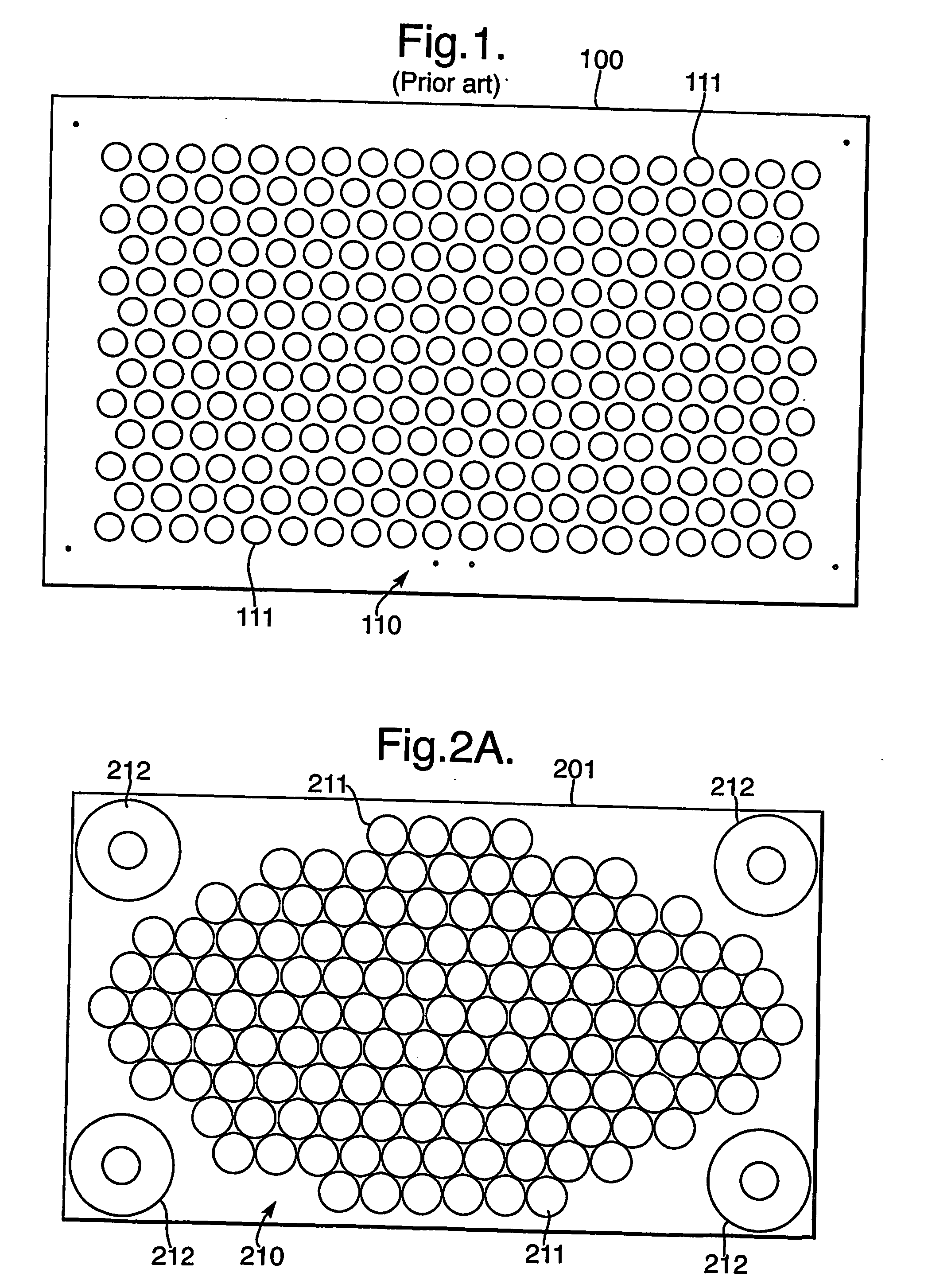
[0058] Referring to FIG. 1, there is shown the front face 100 of a known transducer array loudspeaker system. In the following this system and the new systems according to variants of the present invention will be generally referred to as “Sound Projectors”.

[0059] The known Sound Projector system of FIG. 1 includes an array 110 of 254 transducers 111 each having a diameter of 35 mm. The transducers are arranged on a triangular pitch grid with a rectangular envelope or circumference. The array 110 itself is mounted on a rectangular base plate 101. The overall dimensions of the base plate are 900 mm length and 552 mm height. The transducers 111 are nominally equal having a good sound reproduction across most of the audible spectrum. Given their small diaphragm size the travel of the moving coil system needs to be large to achieve sufficient power and hence the transducers 111 used in the known design are relatively difficult to manufacture and comparatively expensive.

[0060] The prio...


PUM


Abstract

A loudspeaker system is described including an array of electro-acoustic transducers capable of generating steerable beams of sound and additional transducers adapted to reproduce low frequency sound being placed at the perimeter of said array.

Description

FIELD OF THE INVENTION [0001] This invention relates to a device including an array of electro-acoustic transducers capable of generating beams of audible sound. More specifically, it relates to such array devices capable of receiving multiple audio or multi-channel audio input signals and to produce independently steerable and focusable beams of audible sound, at a level suitable for home entertainment or professional sound reproduction applications. BACKGROUND OF THE INVENTION [0002] Recent years have seen widespread use of multi-channel stereophonic sound in audio / visual systems. The trend in the technology has been away from conventional stereo sound reproduction systems, and toward “surround sound” techniques where the sound field is dynamically (and intentionally) shifted to the sides of and behind the listener. [0003] To improve listener perceived characteristics, multi-channel sound reproduction systems are known which include one or more surround-sound channels (often refer...

Claims


Application Information

Patent Timeline
Patent Type & Authority Applications(United States)
IPC IPC(8): H04R3/00H04R1/02H04R9/06H04N5/445H04N5/45H04N5/64H04R1/40H04R3/12H04R5/02
CPCH04N5/45H04N5/642H04R1/403H04R3/12H04R5/02H04R2499/15H04R2201/403H04R2201/405H04R2203/12H04R2205/022H04R2217/03H04R2201/401
Inventor HOOLEY, ANTHONYGOUDIE, ANGUS GAVINLENEL, URSULA RUTHSHEPHERD, MARK RICHARDBIENEK, IRVING ALEXANDER
Owner 1 LIMITED ST JOHN S INNOVATION CENT
Why Eureka
Try Eureka