Ball joint with integrated angle sensor

a ball joint and angle sensor technology, applied in the direction of resistors with plural resistive elements, mechanical devices, transportation and packaging, etc., can solve the problem that the pivot movement of the ball cannot be detected with unsatisfactory accuracy, and achieve the effect of high accuracy

Inactive Publication Date: 2005-04-12
ZF LEMFOERDER METALLWAREN AG
View PDF17 Cites 92 Cited by
  • Summary
  • Abstract
  • Description
  • Claims
  • Application Information

AI Technical Summary

Benefits of technology

The object of the present invention is to create a ball-and-socket joint for a motor vehicle, in which the pivot angle in at least one pivot direction can be determined with high accuracy.

Problems solved by technology

Such a ball-and-socket joint has the drawback that the pivoting movements of the ball pivot can be detected only with unsatisfactory accuracy.

Method used


Image

  • Ball joint with integrated angle sensor
  • Ball joint with integrated angle sensor

Examples


Embodiment Construction

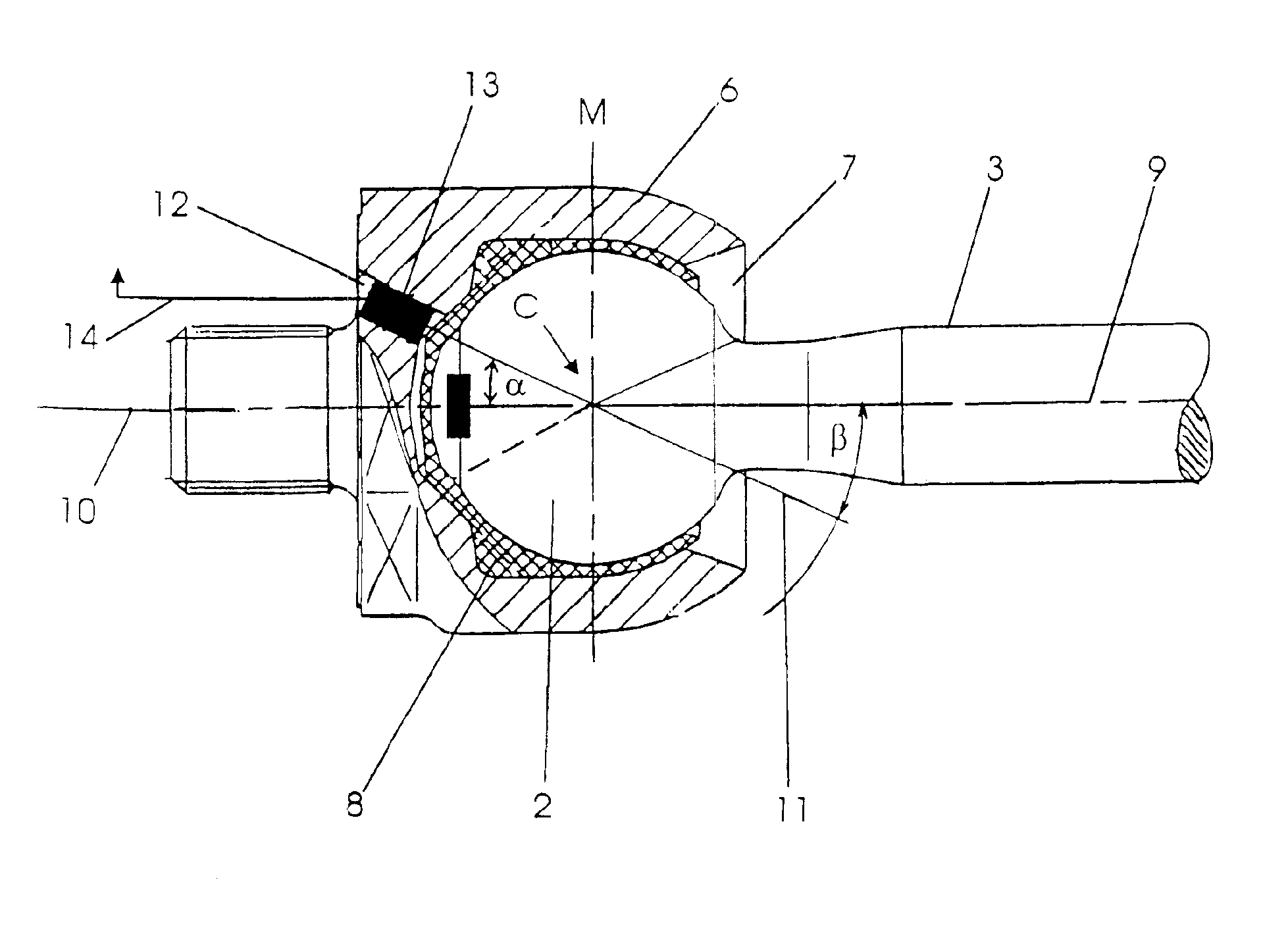
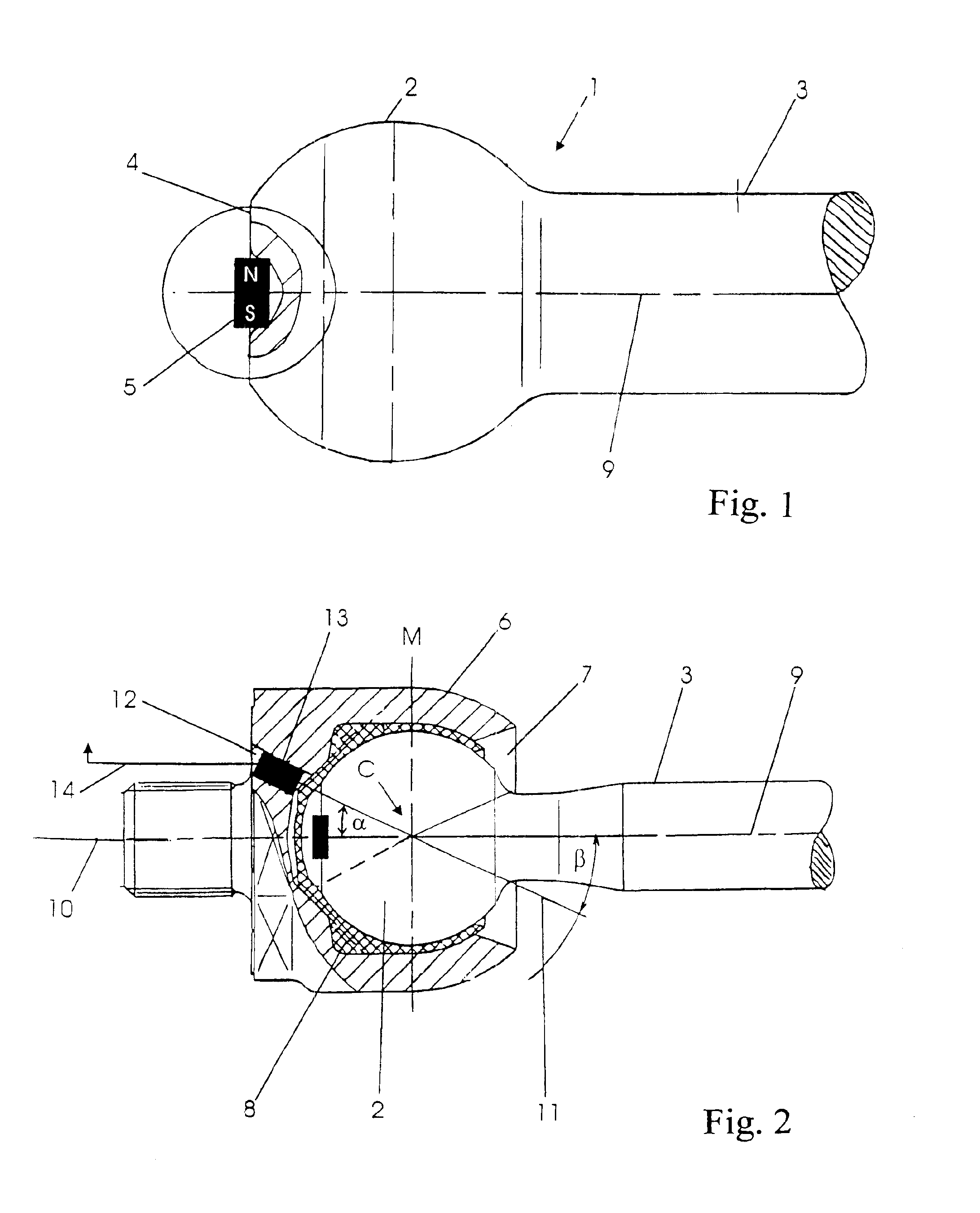
Referring to the drawings in particular, FIG. 1 shows a ball pivot 1 according to an embodiment of the ball-and-socket joint according to the present invention. The ball pivot 1 has a joint ball 2 and a pin 3. The joint ball 2, at its end facing away from the pin 3, has a flattened area 4, in the center of which a permanent magnet 5 is mounted in a recess provided in the joint ball 2, whereby, in the figure, the north pole of the permanent magnet 5 is designated by the letter “N” and the south pole of the permanent magnet 5 is designated by the letter “S.” The permanent magnet 5 is arranged with its two poles N and S on the surface of the flattened area such that these poles have the same distance to the central point of the joint ball 2.

FIG. 2 shows the embodiment of a ball-and-socket joint according to the present invention in the assembled state, whereby the ball pivot 1 is pivotably mounted in a ball-and-socket joint housing 6. The ball pivot 1 projects, with its pin 3, from a j...


PUM


Abstract

A ball-and-socket joint with integrated angle sensor for a motor vehicle, especially for the chassis of the motor vehicle is created. The ball-and-socket joint has a ball-and-socket joint housing (6) provided with a joint opening (7), a ball pivot (1) having a joint ball (2) and a pin (3), which is mounted, with its joint ball (2), rotatably and pivotably in a hollow-ball-shaped bearing surface in the ball-and-socket joint housing (6), and projects, with its pin (3), through the joint opening (7) out of the ball-and-socket joint housing (6). A two-pole field transducer (5) is provided at the end of the joint ball (2) facing away from the pin (3). The poles of the field transducer (5) are arranged on the ball surface. In this case, at least two field sensors (13) are arranged at a distance from one another with respect to the meridian plane defined by the large circle on the hollow-ball-shaped bearing surface running at right angles to the bearing longitudinal axis in the area or on the ball-and-socket joint housing (6) facing away from the joint opening, and interact with the field produced by the field transducer (5).

Description

FIELD OF THE INVENTIONThe present invention pertains to a ball-and-socket joint for a motor vehicle, and particularly for the chassis of the motor vehicle, with a ball-and-socket joint housing provided with a joint opening, a ball pivot having a joint ball and a pin, which ball pivot is mounted, with its joint ball, rotatably and pivotably in a hollow-ball-shaped bearing surface in the ball-and-socket joint housing and projects, with its pin, through the joint opening out of the ball-and-socket joint housing, and a two-pole field transducer provided at the end of the joint ball facing away from the pin, whose poles are arranged on the ball surface.BACKGROUND OF THE INVENTIONSuch a ball-and-socket joint is known from EP 0 617 260 B1, in which case a permanent magnet is arranged on the ball as the field transducer. In the area of the housing directly opposite the magnet in the unejected state of the ball pivot, a magnetoresistive sensor is arranged such that this sensor interacts with...

Claims


Application Information

Patent Timeline
Patent Type & Authority Patents(United States)
IPC IPC(8): B60G17/015B60G17/019B60G7/00F16C11/06
CPCB60G7/005B60G17/019F16C11/0619B60G2204/11B60G2204/416B60G2400/05162B60G2401/172B60G2204/116F16C11/0604F16C11/0633F16C11/0642F16C41/00F16C41/007F16C2233/00F16C2326/05
Inventor KRUSE, JOCHEN
Owner ZF LEMFOERDER METALLWAREN AG
Why Eureka
Try Eureka