Compact printed "patch" antenna

a technology of printed antennas and patch antennas, applied in the direction of waveguide devices, substantially flat resonant elements, resonant antennas, etc., can solve the problems of narrow bandwidth, difficult to integrate the antenna into an array, and relatively inefficient antennas, etc., to achieve the effect of reducing the antenna siz

Inactive Publication Date: 2005-04-12
GULA CONSULTING LLC
View PDF5 Cites 106 Cited by
  • Summary
  • Abstract
  • Description
  • Claims
  • Application Information

AI Technical Summary

Benefits of technology

The raised portion which can have a cross section in the plane of symmetry that is rectangular, sinusoidal, trapezoidal or triangular, has a height substantially equal to half the distance between the lengths of the longer and shorter sides of the layer, which is rectangular, extending over and along the raised portion. However, the height of the raised portion is generally chosen as a function of the intended compactness of the antenna; as the height of the raised portion increases, the size of the antenna decreases.
The other face of the substrate can include another raised portion extending lengthwise of the plane of symmetry and covered by the other conductive layer.
For an antenna with crossed polarizations, in particular circular or elliptical polarization, one face of the substrate includes two mutually perpendicular raised portions forming a striking cross, extending lengthwise of two respective planes of symmetry of the antenna. The conductive layer of the antenna extending over and along the raised portions can occupy a rectangular or square surface on the dielectric substrate whose sides are the same lengt

Problems solved by technology

If the dielectric substrate is thin and has a high dielectric permittivity, the antenna is relatively inefficient and its bandwidth

Method used


Image

  • Compact printed "patch" antenna
  • Compact printed "patch" antenna
  • Compact printed "patch" antenna

Examples


first embodiment

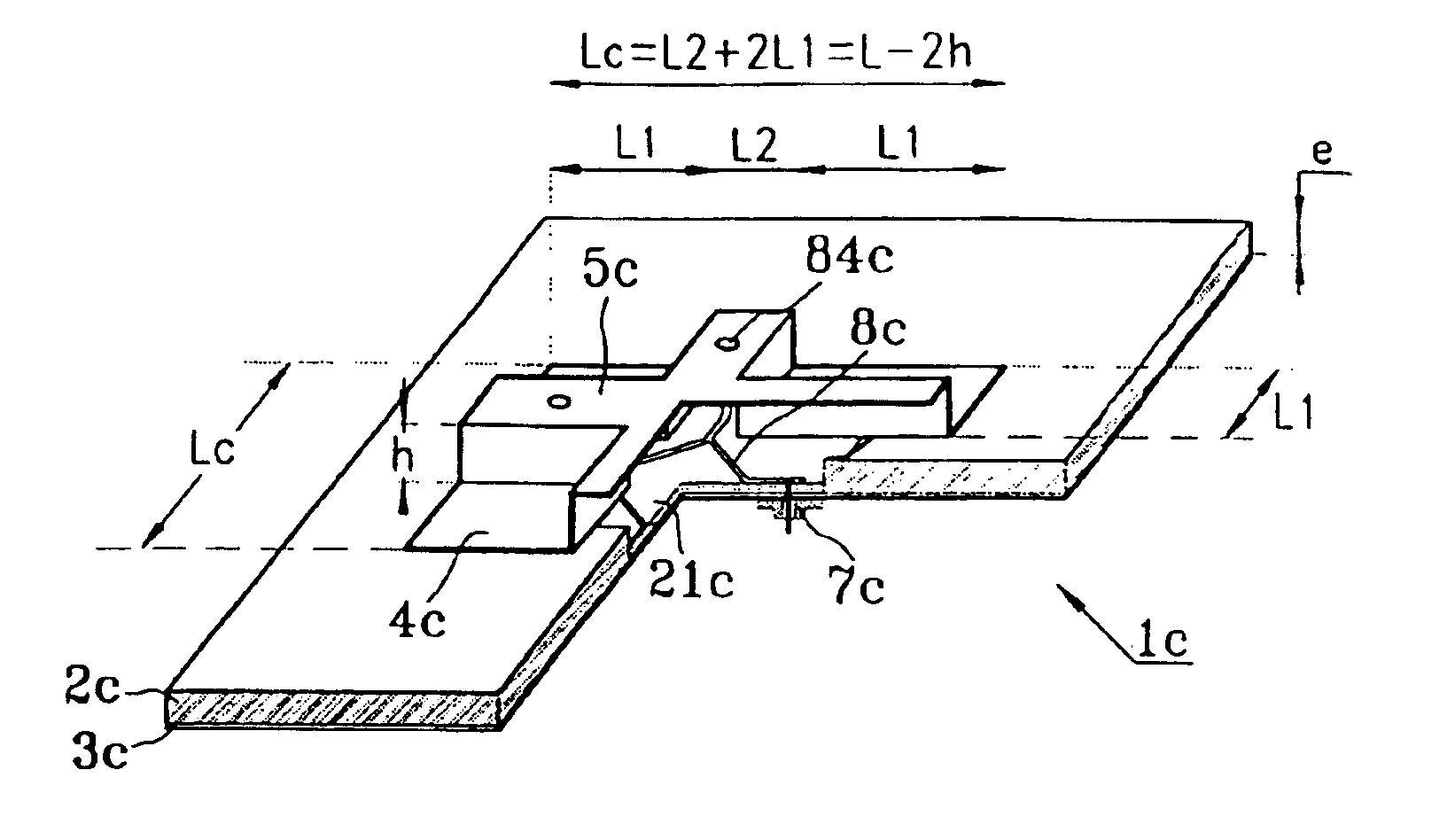
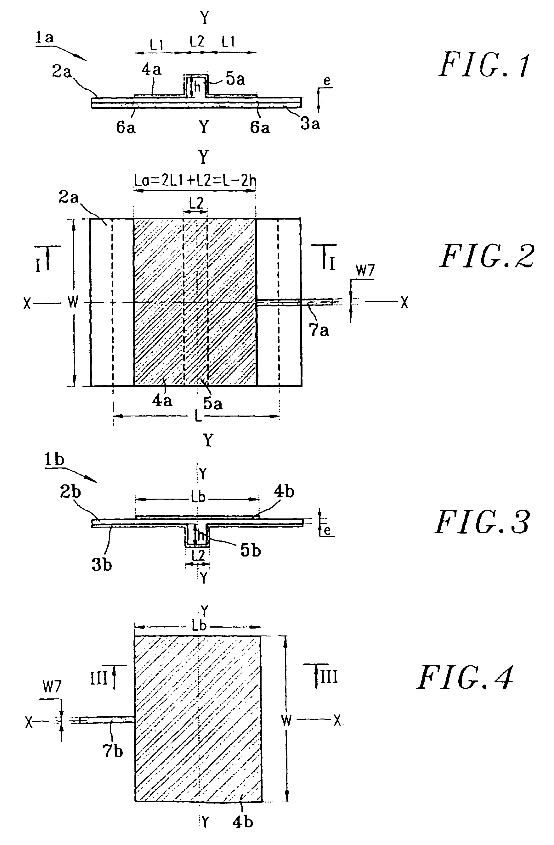
Referring to FIGS. 1 and 2, a “patch” half-wave printed antenna 1a with linear polarization conforming to the invention includes a dielectric substrate 2a, a first electrically conductive layer 3a on a first face of the substrate and constituting a ground plane, and a rectangular second electrically conductive layer 4a at the center of the second face of the substrate and having a parallelepiped-shaped central raised portion 5a. The second conductive layer 4a has a rectangular contour and covers the top and the longitudinal sides of the raised portion 5a. The antenna therefore has a structure which is symmetrical with respect to a plane of symmetry YY perpendicular to the faces of the substrate 2a and lengthwise of the raised portion 5a. The layer 4a has a U-shaped section with projecting ends, as shown in FIG. 1, with wings on the second face of the substrate 2a having a width L1 much greater than the width L2 of the raised portion 5a. Generally speaking, the height h of the raised...

second embodiment

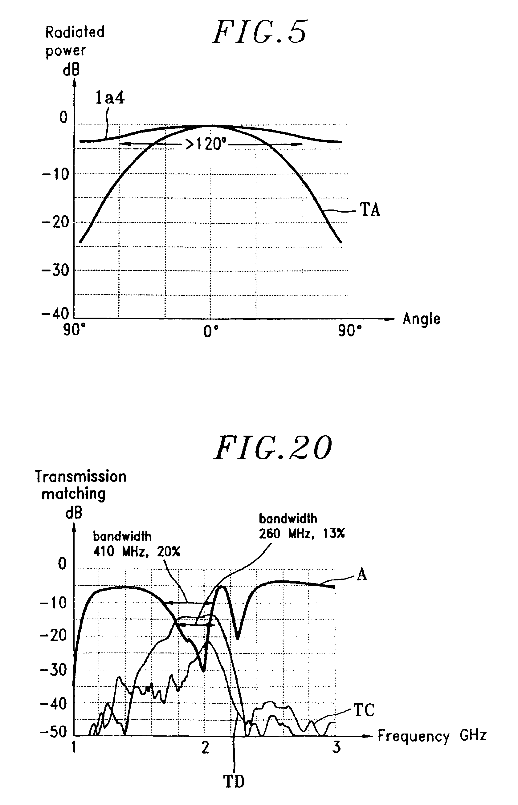
Similar results have been obtained for antennas 1b1 to 1b4 conforming to the invention, with a conformal ground plane 3b with a raised portion 5b, as shown in table 2 below, again for antennas with the dimensions Lb=L=50 mm and e=2 mm.

TABLE 2TA test1b11b21b31b4h (mm)02468Resonant2.632.32.091.951.82frequency(GHz)Bandwidth1.7%1.9%2.1%2.3%2.5%Directivity9.47.976.46.1(dB)

A preferred method for fabrication of a linear polarization antenna according to the invention includes four steps E1, E2, E3 and E4 shown in FIGS. 6-7, 8-9, 10-11 and 12-13, respectively.

In the initial step E1, fabrication starts with a thin block of foam BL of thickness h+e, of width greater than W and of length greater than La. The dielectric material of the block BL, into which the dielectric substrate 2a will be machined, has a typical relative permittivity of the order of 1.07, in conjunction with a length L=50 mm<λr / 2 with λr=λ / √{square root over (εr)}, where λ is the wavelength corresponding to a frequency ...


PUM

PropertyMeasurementUnit
Fractionaaaaaaaaaa
Fractionaaaaaaaaaa
Fractionaaaaaaaaaa

Abstract

A half-wave printed “patch” antenna includes, symmetrically with respect to a plane of symmetry of the antenna perpendicular to faces of the antenna, a dielectric substrate and two conductive layers on respective faces of the substrate. One face of the substrate includes a raised portion extending lengthwise of the plane of symmetry and one of the conductive layers extends over and along said raised portion. Consequently, the antenna has a small size, combined with a more open radiation diagram. The antenna includes only one raised portion for linear polarization, or two raised portions or a raised portion with axial symmetry for crossed polarizations.

Description

BACKGROUND OF THE INVENTION1. Field of the InventionThe present invention relates to a plated technology “patch” printed antenna, for operation with linear or circular polarization at frequencies of the order of a few gigahertz. In particular, the antenna is intended to be replicated in order to be integrated into an array for receiving and / or sending telecommunication signals on board a craft, such as a satellite in low earth orbit, or to be installed in a base station in communication with a telecommunication satellite, or to be installed in a base station for radio communications with mobile terminals.2. Description of the Prior ArtThe invention is more particularly directed to a “patch” half-wave printed antenna including a dielectric substrate and two conductive layers on respective faces of the substrate. One of the layers constitutes a ground plane. The other layer is a rectangular or square conductive plate known as a “patch”. This kind of individual printed antenna is easy ...

Claims


Application Information

Patent Timeline
IPC IPC(8): H01Q9/04
CPCH01Q9/0407H01Q9/0471H01Q9/0428Y10T29/49016
Inventor TOUTAIN, YANNCOUPEZ, JEAN-PHILIPPEBLOT, JEAN-PIERRE
Owner GULA CONSULTING LLC
Why Eureka
Try Eureka