Front-illuminating device and a reflection-type liquid crystal display using such a device

a technology of reflection-type liquid crystal display and front-illuminating device, which is applied in the direction of optics, instruments, optical light guides, etc., can solve the problems of difficult to put this type of lcd into practical use, degradation of display quality, and back light, as used in transmission-type lcds, etc., and achieve the effect of improving the efficiency of light us

Inactive Publication Date: 2005-04-12
SHARP KK
View PDF44 Cites 157 Cited by
  • Summary
  • Abstract
  • Description
  • Claims
  • Application Information

AI Technical Summary

Benefits of technology

The present invention has been devised so as to solve the above-mentioned problems, and its objective is to provide a front-illuminating device for improving the efficiency of use of light in the light source and for illuminating an object to be illuminated uniformly and more brightly, and also to provide a reflection-type liquid crystal display using such a front-illuminating device.
The above-mentioned arrangement makes it possible to prevent the occurrence of Moire fringes, etc. due to interference between the periodic structure and the pixel arrangement, and consequently to prevent double images. As a result, it becomes possible to further improve the display quality of the reflection-type LCD. In addition, in the above-mentioned arrangement, since the front-illuminating means is formed by one sheet of a light-directing body, it is possible to obtain a thin, light-weight illuminating means, and also to prevent the occurrence of Newton rings in the resulting images.

Problems solved by technology

However, although it has the above-mentioned advantages, the reflection-type LCD also has the following problem.
Moreover, the above-mentioned problem is particularly aggravated in those reflection-type LCDs using color filters for color display and those reflection-type LCDs using polarizing plates, and an auxiliary illuminating means is required in case of insufficient ambient light.
However, in the reflection-type liquid crystal cell used for the reflection-type LCD, since a reflective plate made of a metal thin-film, etc. is placed on the back surface of the liquid crystal layer, a back light, as used in the transmission-type LCD, can not be used as an auxiliary illuminating means.
LCDs using a half-mirror as a reflective plate, called the semi-transmission-type LCDs, have been proposed; however, the display characteristics thereof merely end up with those somewhat in the middle of the transmission-type LCD and the reflection-type LCD, and it seems to be difficult to put this type of LCDs into practical use.
Here, in the surface light-emitting source device 700 disclosed in the above-mentioned Laid-Open Patent Application (1), Moire fringes tend to occur due to interference between the periodic protruding and recessed portions 702 formed on the light-directing body 703 and the repeating direction (not shown) of the pixels formed on the reflection-type LCD 705, resulting in degradation in the display quality.
However, Laid-Open Patent Application (1) does not disclose anything about techniques for addressing the above-mentioned problem.
In other words, the system fails to provide good efficiency in the use of light.
These problems are commonly seen in most of the conventional front-light systems.
Consequently, the use of such front-light systems fails to illuminate an object to be illuminated (such as the reflection-type LCD) with a sufficient quantity of light.
However, even in the above-mentioned arrangement, interference tends to occur between periodic structures 902 formed on the first light-directing body 900a and the second light-directing body 900b and the repeating direction of pixels formed on the reflection-type LCD, resulting in a problem of Moire fringes.
Without ensuring such precision in the space, Newton rings occur between the first light-directing body 900a and the second light-directing body 900b, resulting in a problem of serious degradation in the display quality.
As a result, the brightness of the reflection-type LCD that displays images by reflecting external light is reduced, resulting in difficulty in achieving thinness and light weight.

Method used


Image

  • Front-illuminating device and a reflection-type liquid crystal display using such a device
  • Front-illuminating device and a reflection-type liquid crystal display using such a device
  • Front-illuminating device and a reflection-type liquid crystal display using such a device

Examples


embodiment 1

[Embodiment 1]

Referring to Figures, the following description will discuss one embodiment of the present invention.

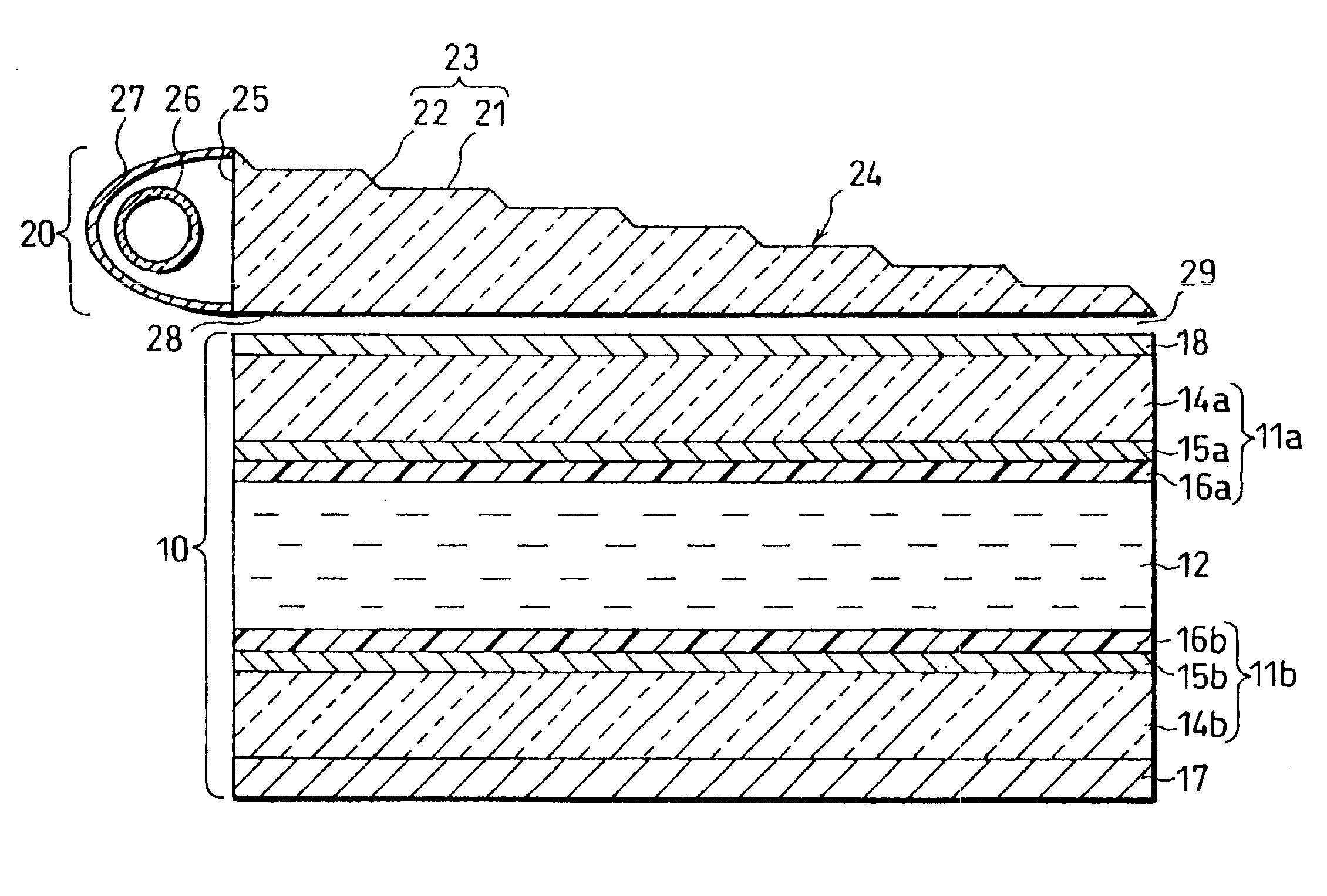
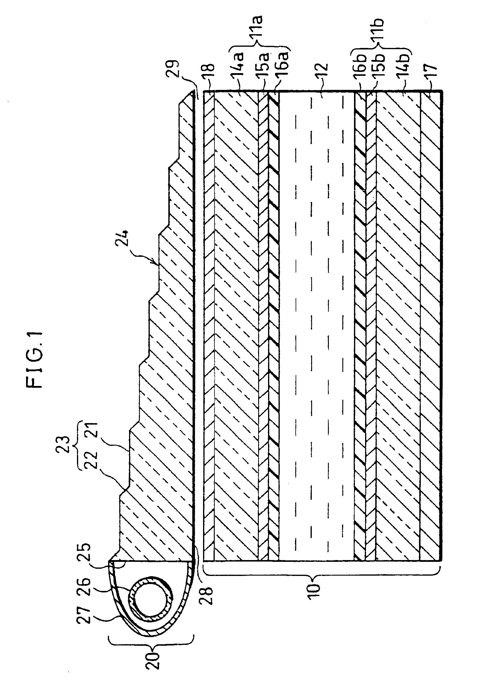
As illustrated in FIG. 1, the reflection-type LCD of the present embodiment is provided with a front light 20 (a front-illuminating device) placed in front of a reflection-type liquid crystal cell 10 (a reflection-type liquid crystal element).

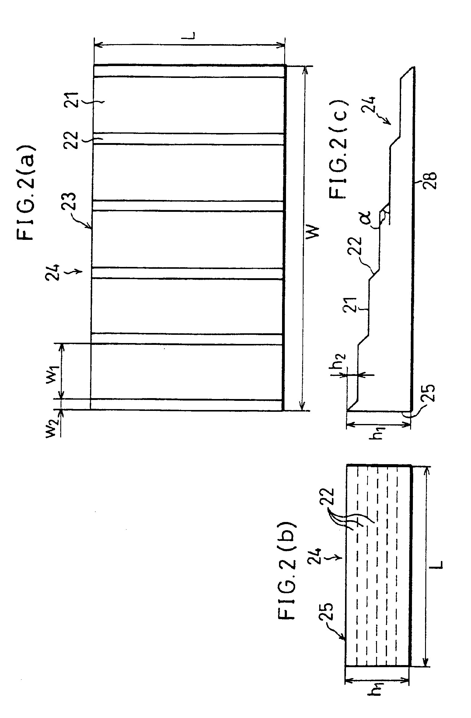
The front light 20 is mainly constituted by a light source 26 and a light-directing body 24. The light source 26, which is a line-shaped light source such as, for example, a fluorescent tube, is placed along the side face (incident surface 25) of the light-directing body 24. The light-directing body 24 is designed so that its interface 28 (a first light-releasing surface) on the liquid crystal cell 10 side has a flat shape. Its interface 23 (a second light-releasing surface), which faces the interface 28 in the light-directing body 24, is, on the other hand, designed so that flat portions 21, which are formed parallel to or virtual...

embodiment 2

[Embodiment 2]

Referring to Figures, the following description will discuss another embodiment of the present invention. Here, those members that have the same functions and that are described in Embodiment 1 are indicated by the same reference numerals and the description thereof is omitted.

As illustrated in FIG. 8, the reflection-type LCD in accordance with the present embodiment is characterized in that a front-light system 51, constituted by the front light 20 (the first light-directing body) described in Embodiment 1 and a wedge-type second light-directing body 40, is provided in front of the liquid crystal cell 10.

The second light-directing body 40 is placed between the light-directing body 24 of the front light 20 and the liquid crystal cell 10, and is designed to have a slanting face 41 that is parallel to the interface 28 of the light-directing body 24 and a bottom surface 42 that is parallel to the surface of the liquid crystal cell 10. As illustrated in FIG. 9(a), on the i...

embodiment 3

[Embodiment 3]

Referring to Figures, the following description will discuss still another embodiment of the present invention. Here, those members that have the same functions and that are described in the aforementioned Embodiments are indicated by the same reference numerals and the description thereof is omitted.

As illustrated in FIG. 12, the reflection-type LCD in accordance with the present embodiment is characterized in that a front-light system 52, constituted by the front light 20 and a light-directing body 45, is provided in front of the liquid crystal cell 10.

As illustrated in FIG. 13, the second light-directing body 45 functions as a front-diffusing plate for diffusing light that is made incident thereon from the light-directing body 24 only in its proceeding direction, and also functions as an anisotropic diffusing plate for diffusing only light that is incident thereon from within a predetermined angle range, while transmitting light that is incident thereon from out of ...


PUM

PropertyMeasurementUnit
angle of inclinationaaaaaaaaaa
widthaaaaaaaaaa
widthaaaaaaaaaa

Abstract

Featured are a front-illuminating device including a light source and first and second light-directing bodies. The first light-directing body is disposed in front of an object to be illuminated and has a first light-releasing surface from which light is released to the object to be illuminated and a second light-releasing surface, placed face to face with the first light-releasing surface, for releasing light reflected from the object to be illuminated. The second light-releasing surface also is formed into a step shape and includes slanting portions that reflect light mainly from the light source toward the first light-releasing surface. The second light-directing body is disposed between the first light-directing body and the object to be illuminated and is configured and arranged so a distance from each of the slanting portions to the surface of the second light-directing body second surface is essentially uniform.

Description

FIELD OF THE INVENTIONThe present invention relates to a front-illuminating device which is placed in use between an object to be illuminated and an observer so as to illuminate the object with light and which is designed to transmit reflected light from the object so that the reflected light can be visualized to the observer and a reflection-type liquid crystal display having such a front-illuminating device and a reflection-type liquid crystal cell, and more particularly concerns a front-illuminating device for carrying out efficient illumination without causing degradation in the display quality of the reflection-type liquid crystal cell, and a thin, light-weight, low-power-consumption reflection-type liquid crystal display that uses such a front-illuminating device as an auxiliary light source and that is used for image display in apparatuses, such an information display system and an OA system.BACKGROUND OF THE INVENTIONDifferent from other displays such as CRTs (Cathode Ray Tu...

Claims


Application Information

Patent Timeline
Patent Type & Authority Patents(United States)
IPC IPC(8): G02F1/1335G02F1/13F21V8/00G02B6/00G02F1/13357
CPCG02B6/0025G02B6/0043G02B6/005G02B6/0065G02B6/0076G02F1/133615G02B6/002G02B6/0038G02F2001/133626G02F1/133504G02F2001/133616G02B6/0056G02F1/133616G02F1/133626
Inventor SAWAYAMA, YUTAKASUMIDA, YUKIHIROMASUDA, TAKESHIEBI, TSUYOSHI
Owner SHARP KK
Why Eureka
Try Eureka