Optical waveguide monitoring

Inactive Publication Date: 2005-04-12
OMNIGUIDE
View PDF15 Cites 58 Cited by
  • Summary
  • Abstract
  • Description
  • Claims
  • Application Information

AI Technical Summary

Benefits of technology

This patent describes how to monitor changes in signals sent through an optical fiber to measure its quality. By analyzing these signals, researchers can determine if there are any areas where the fiber may have unevenness or other issues with its performance. Additionally, they can use this data to identify specific locations within the fiber where certain types of damage might occur over time.

Problems solved by technology

This patent discusses how optical waves travel inside optical fibers made of glass or plastic materials. These fibers allow us to transmit data quickly and securely across long distances without losing much energy. However, there may be some small amounts of energy lost when the laser beam passes through the material. This problem is called transmission loss. There are many ways this could happen, but we'll focus on two main ones: scanning and absorption. To address these issues, researchers develop methods to measure and reduce the loss of optical signal quality during production and installation of optical fibers.

Method used


Image

  • Optical waveguide monitoring
  • Optical waveguide monitoring
  • Optical waveguide monitoring

Examples


Embodiment Construction

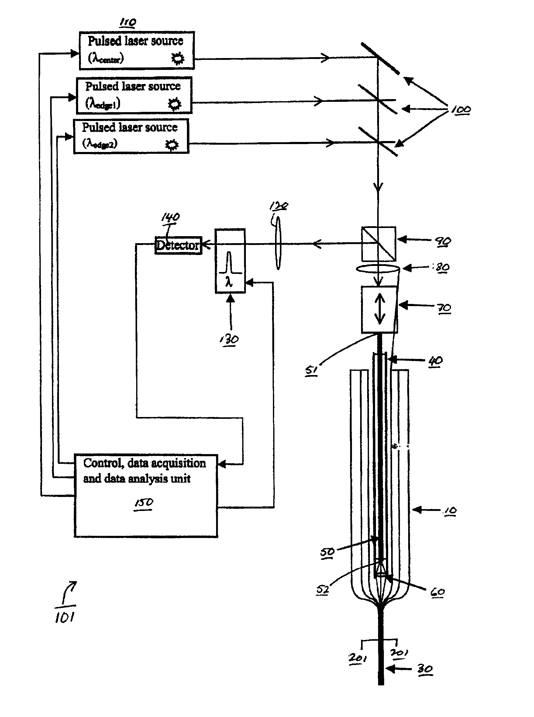
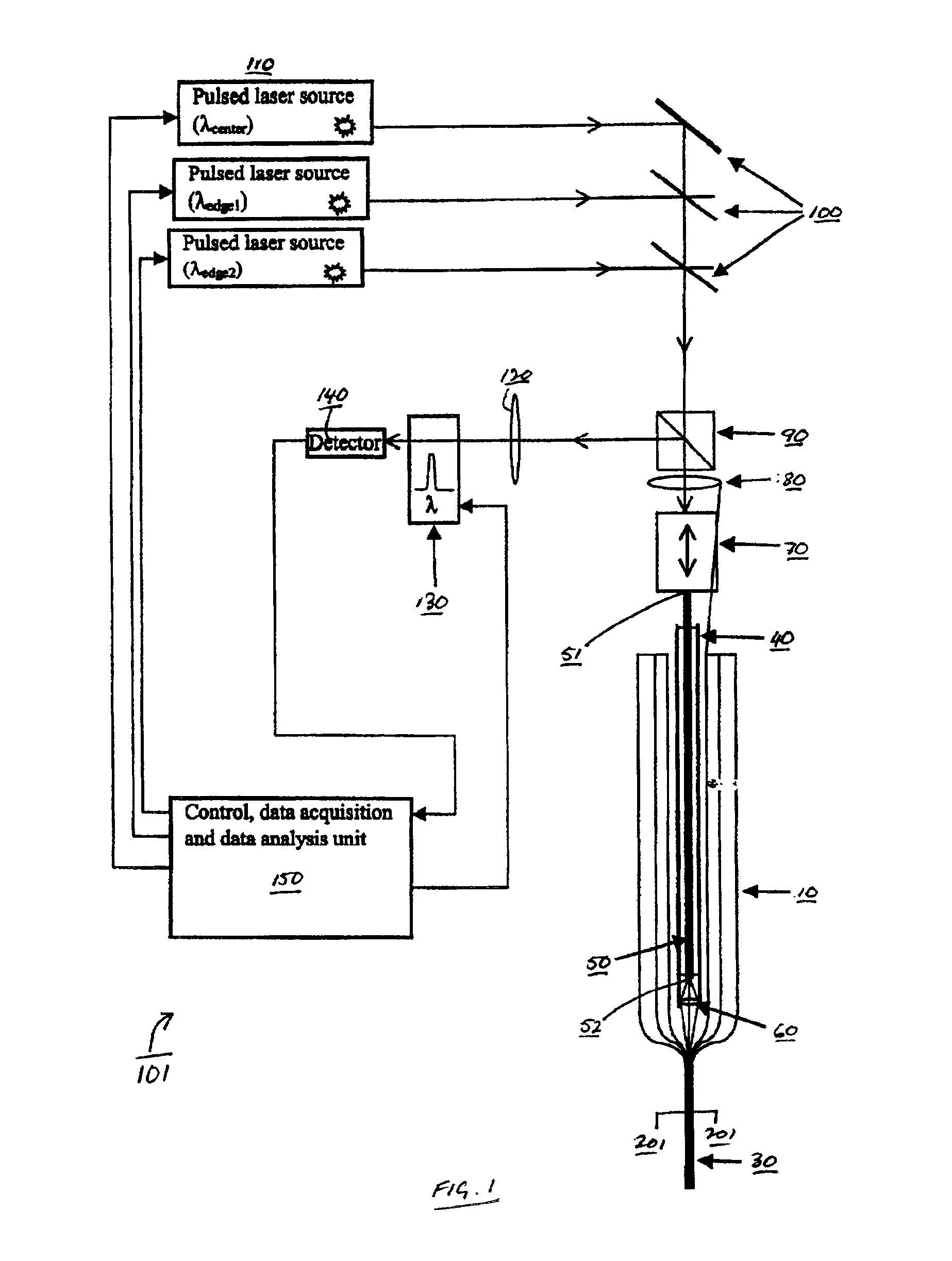
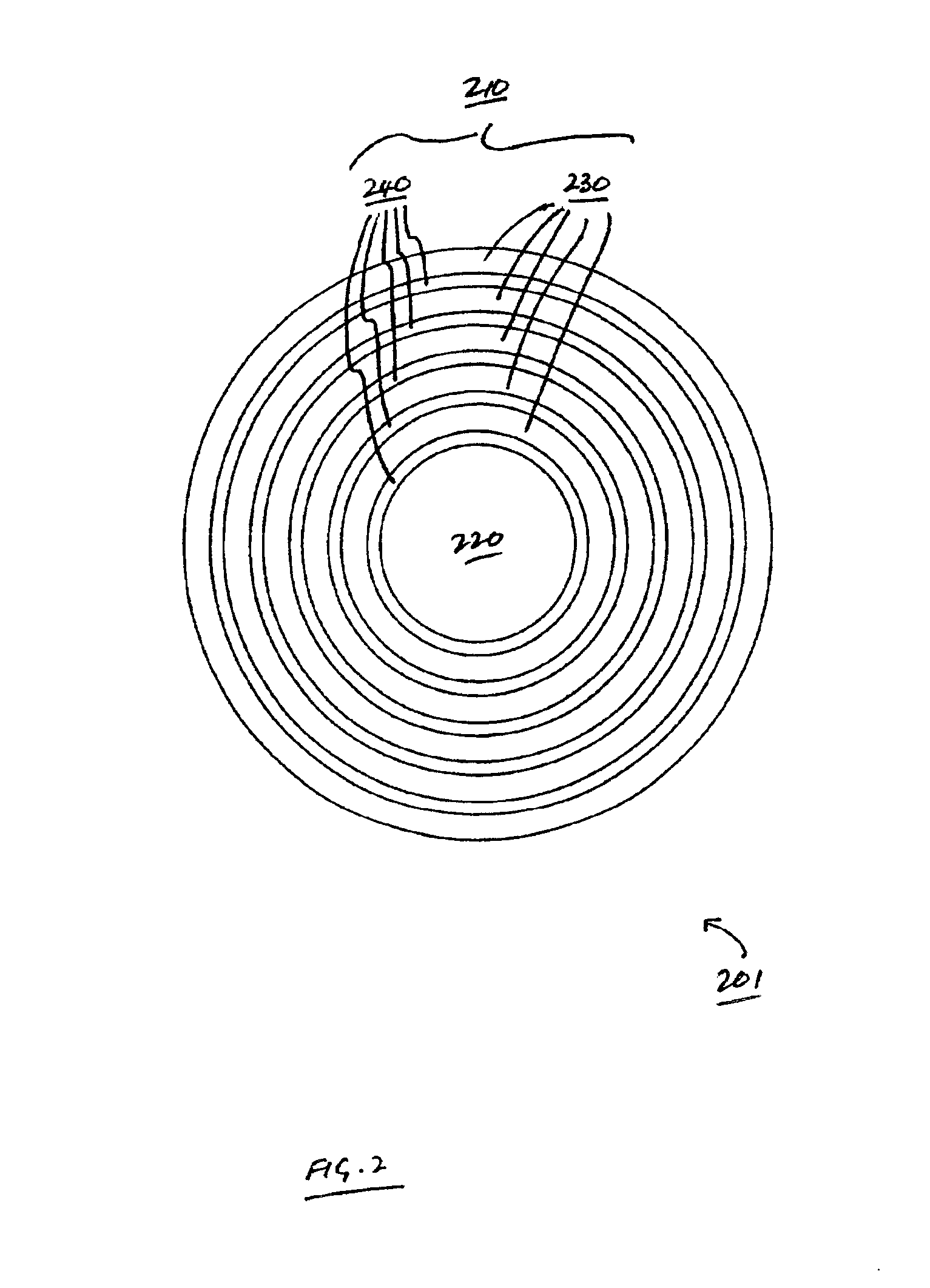
The invention features methods for detecting defects in and monitoring the transmission loss of an optical waveguide, during, for example, drawing or cabling of an optical waveguide. For example, the invention relates to monitoring the quality (e.g., monitoring transmission loss and detecting structural and compositional defects) of optical waveguides that utilize photonic bandgap confinement mechanisms for guiding light (referred to here as photonic crystal fibers), including hollow fibers. In general, defects refer to any structural, compositional or other perturbation of the fiber from its ideal design, which can affect the optical and / or mechanical performance and reliability of the fiber. Examples of defects include perturbations to core radius, perturbations to the layer thickness, delamination between layers, bubbles, particle inclusions in the core or layers, and compositional variations in the layers affecting the refractive index of the layers.

Fiber monitoring is performed...


PUM


Abstract

Techniques for monitoring the quality (e.g., optical and mechanical properties) in optical waveguides (e.g., photonic crystal fibers) are disclosed. Additionally, techniques for detecting and localizing defects in the waveguides are also described. Pulses of light are launched into one end of an optical waveguide. The amount of light scattered out of the same end of the waveguide (i.e., a backscattered or reflected signal) is monitored at certain wavelengths specific to the spectral characteristics of the waveguide. Transmission characteristics and defect localization can be determined from the backscattered signal.

Description


Claims


Application Information

Patent Timeline
Owner OMNIGUIDE
Why Eureka
Try Eureka