Optical deflection apparatus and optical deflection method

a laser light and optical deflection technology, applied in the field of optical deflection apparatus and optical deflection method, can solve the problems of inability to control liquid crystal prisms easily, the conventional method is not suitable for a light-weighted and small system, and the use that requires reduced power consumption

Inactive Publication Date: 2005-04-12
CITIZEN WATCH CO LTD
View PDF7 Cites 17 Cited by
  • Summary
  • Abstract
  • Description
  • Claims
  • Application Information

AI Technical Summary

Problems solved by technology

It is required in the conventional method, however, to control a relatively large mirror with a large physical operation.
Therefore, the conventional method is not suitable for a light-weighted and small system as well as for the use that requires reduced power consumption.
As for the liquid crystal prism having the prismatic liquid crystal layer, the process steps are complicated and moreover the liquid crystal prism can not be controlled easily.

Method used


Image

  • Optical deflection apparatus and optical deflection method
  • Optical deflection apparatus and optical deflection method
  • Optical deflection apparatus and optical deflection method

Examples


Embodiment Construction

Exemplary embodiments of the optical deflection apparatus and optical deflection method according to the present invention are explained below with reference to the accompanying drawings.

1-1. Configuration of an Optical Deflector

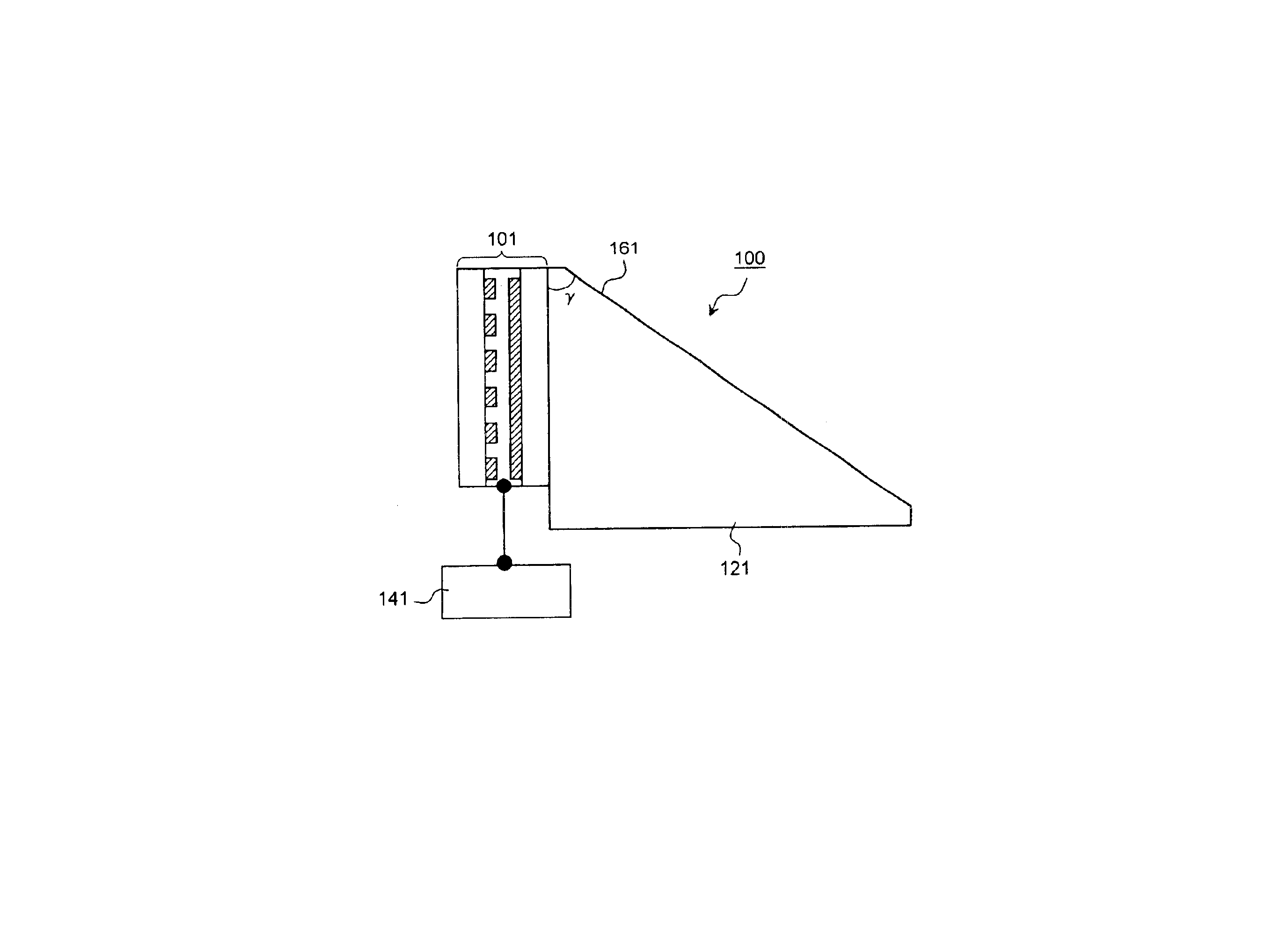
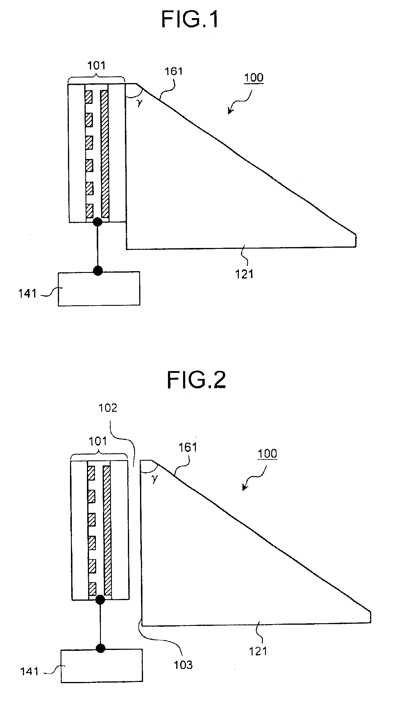
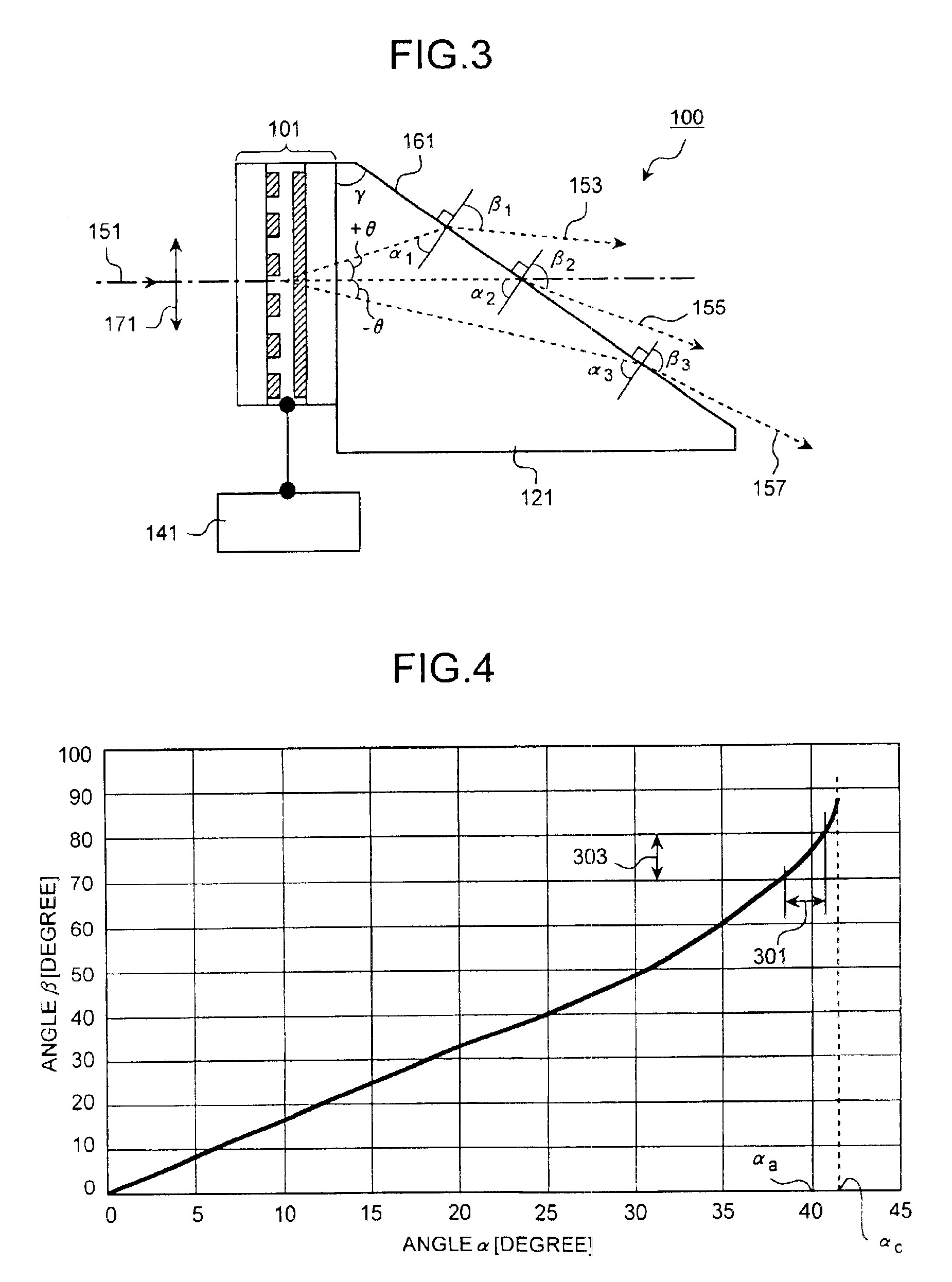
Configuration of the optical deflection apparatus according to an embodiment of the present, invention is explained first using FIGS. 1 to 3. FIGS. 1 and 2 are structural cross-sectional views that show configurations of an optical deflection apparatus 100 in the embodiment.

The optical deflection apparatus 100 comprises a liquid crystal optical phase modulator 101, and a wedge-shape (hereinafter “wedged prism”) prism 121 having an emittance surface 161 tilting at a certain angle of γ. A driver 141 is connected to the liquid crystal optical phase modulator 101.

The emittance surface 161 of the wedged prism 121 makes a contact with the air, therefore, an anti-reflection coat may be formed on it to prevent any reflection from occurring at an air-substrate interf...


PUM

PropertyMeasurementUnit
transparentaaaaaaaaaa
widthaaaaaaaaaa
refractive indexaaaaaaaaaa

Abstract

A liquid crystal optical phase modulator includes first and second substrates. A plurality of strip-shaped individual electrodes that are arranged parallel to each other on one surface of the first substrate. A common electrode is arranged on one surface, which faces towards the surface of the first substrate, of the second substrate. Both the individual electrodes and the common electrode are made of a conductive material that is transparent. A driver unit drives the liquid crystal optical phase modulator. A wedge-shaped prism is located near another surface of the second substrate of the liquid crystal optical phase modulator. The prism is such that a surface of it from where a light enters and a surface of it from where the entered light is output make a predetermined angle with each other.

Description

BACKGROUND OF THE INVENTION1) Field of the InventionThe present invention relates to an apparatus for and method of deflecting a laser light.2) Description of the Related ArtOptical technologies for deflecting laser light have been applied in various fields. Examples where these technologies are used are an aberration compensation system for free-space optics and a scanning system for laser radar.A gimballed mirror is frequently employed as an optical deflection apparatus for laser light and an optical system for pointing. The method of employing the gimballed mirror is direct and simple because the mirror can be moved mechanically to control the direction of the laser light.There are technologies in the art associated with a liquid crystal prism having a prismatic liquid crystal layer (see Japanese Patent Application Laid-Open No. 6-194695, Japanese Patent Application Laid-Open No. 7-92507, for example).It is required in the conventional method, however, to control a relatively lar...

Claims


Application Information

Patent Timeline
Patent Type & Authority Patents(United States)
IPC IPC(8): G02B26/08G02F1/29G02F1/1335G02F1/13
CPCG02B26/0816G02F1/292G02B27/0087G02F1/1335
Inventor IDE, MASAFUMI
Owner CITIZEN WATCH CO LTD
Why Eureka
Try Eureka