Disk drive writer with active reflection cancellation

a technology of active reflection and write circuit, which is applied in the direction of driver circuits, instruments, data recording, etc., can solve the problems of limiting the performance of the write circuit, compromising the performance of the circuit, and unable to achieve impedance matching to the interconnect of the write circui

Inactive Publication Date: 2005-04-12
AVAGO TECH INT SALES PTE LTD
View PDF5 Cites 15 Cited by
  • Summary
  • Abstract
  • Description
  • Claims
  • Application Information

AI Technical Summary

Problems solved by technology

However, these improved write circuits have been unable to achieve impedance matching to the interconnect.
Such impedance matching would require a small resistor in parallel with the write head which would shunt some of the write current away from the write head during operation of the circuit and thereby compromise the performance of the circuit.
The lack of impedance matching results in pattern dependent distortion which limits the performance of the write circuit.
The impedance matching of this circuit improves the write driver's performance, but also results in a decrease in the voltage delivered by the write driver preamplifier caused by the voltage drop across the series impedance matching resistor.

Method used


Image

  • Disk drive writer with active reflection cancellation
  • Disk drive writer with active reflection cancellation
  • Disk drive writer with active reflection cancellation

Examples


Embodiment Construction

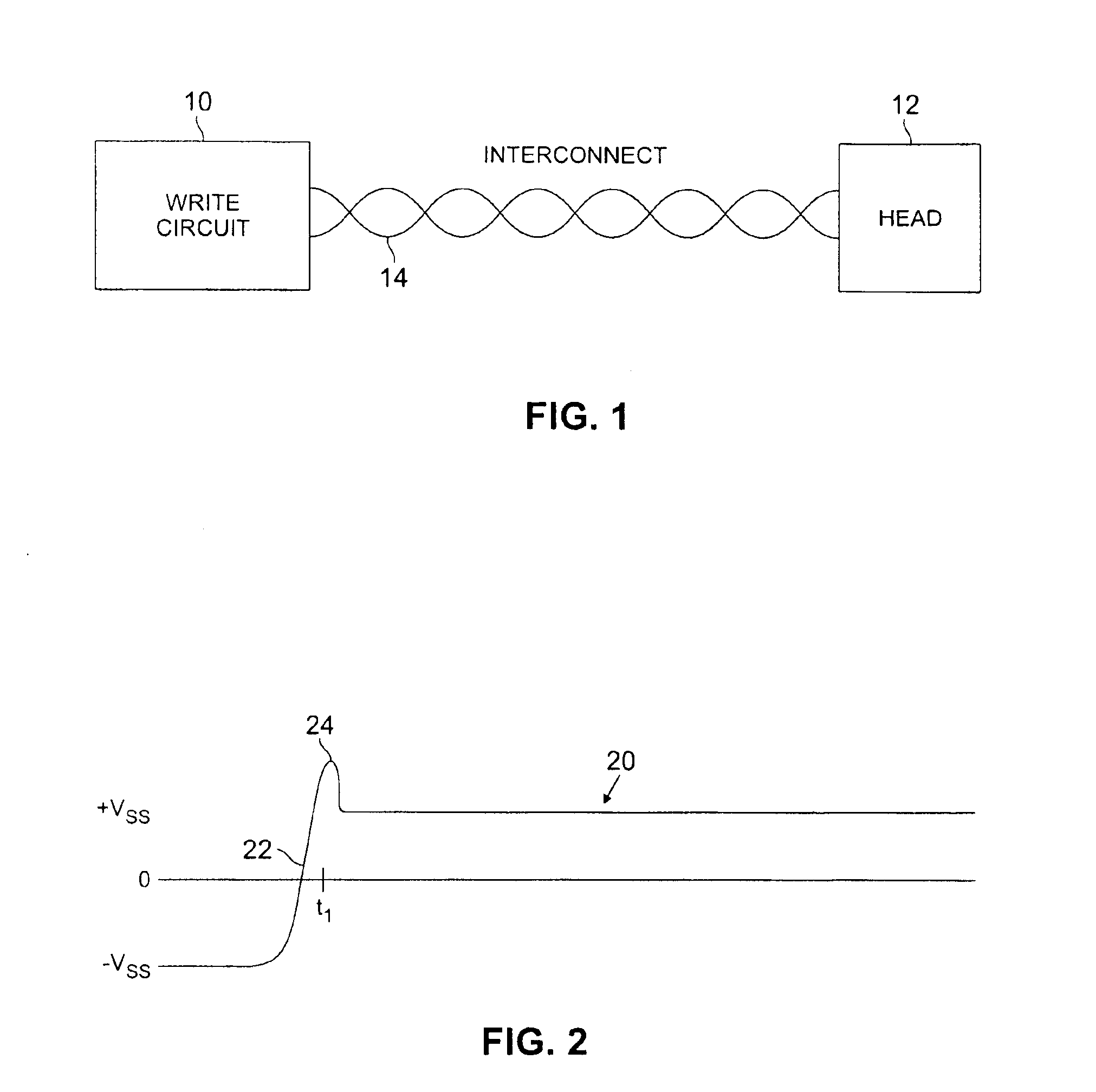
FIG. 1 is a diagram illustrating write circuit 10 connected to write head 12 via interconnect 14, in a manner common to storage devices such as disk drives. While write head 12 is located to interact with the storage medium (such as a disk) directly, write circuit 10 is typically located remotely from write head 12, which is why interconnect 14 is required to connect write circuit 10 to write head 12.

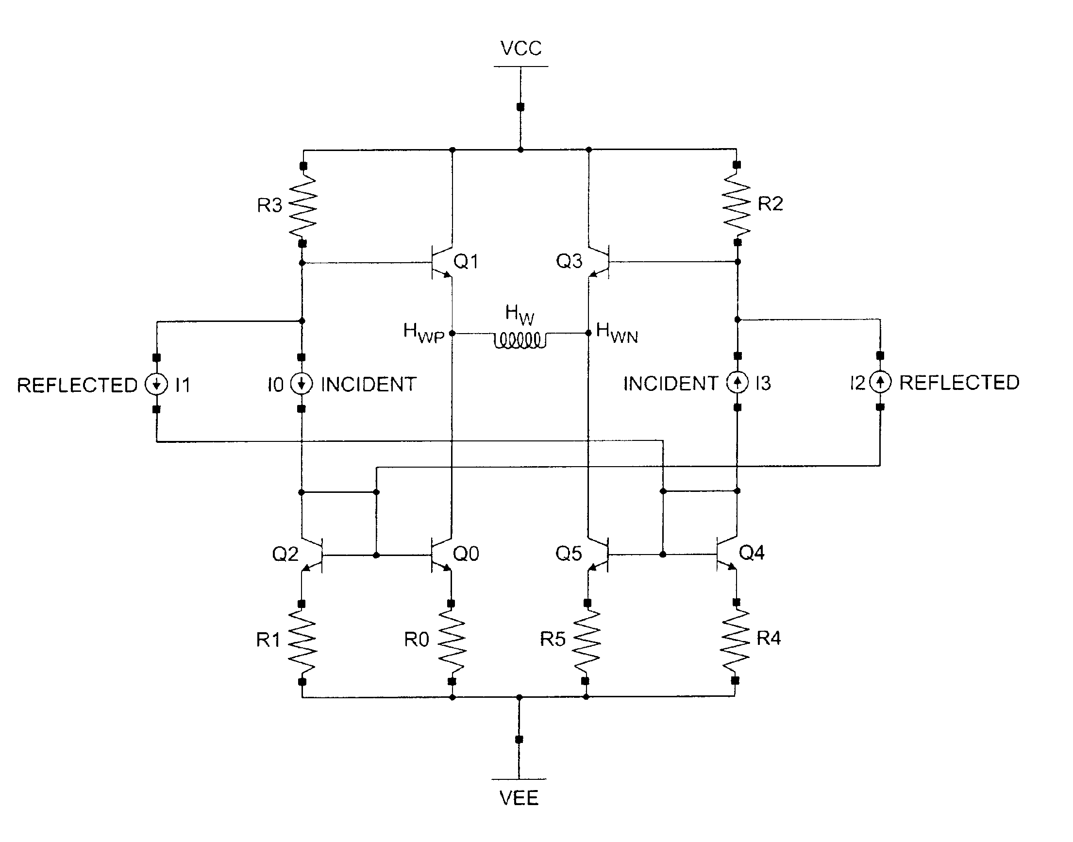
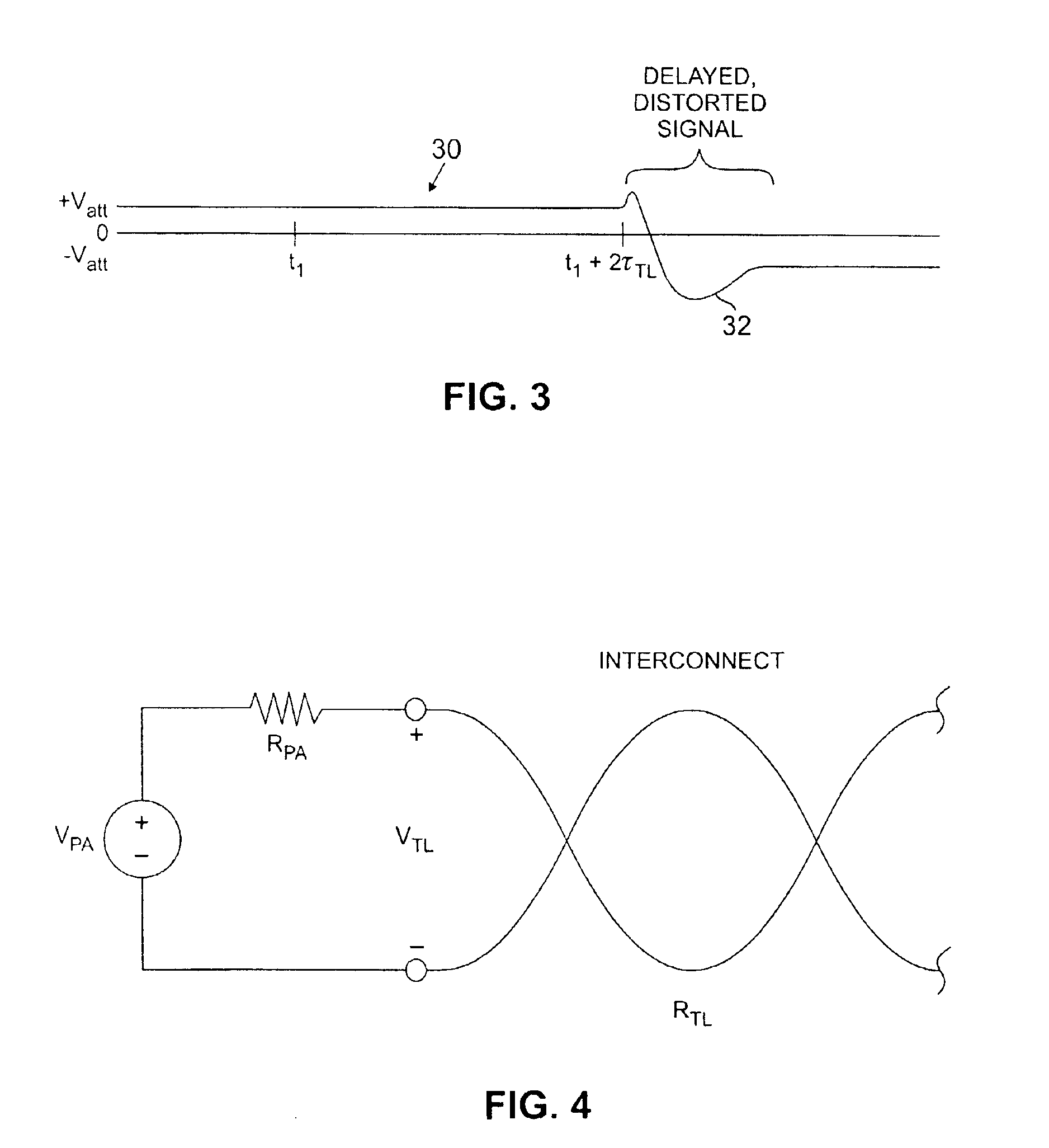
Interconnect 14 has a characteristic impedance which is mismatched with the impedances of write circuit 10 and write head 12. In an exemplary configuration, interconnect 14 has 100 Ohms differential impedance (Zdiff) and 30 Ohms common-mode impedance (Zcm), and write head 12 has 7 nano-Henries of inductance (L) in parallel with 200 Ohms parallel resistance (Rp) with a series resistance of 10 Ohms (Rs) in series with the parallel L-Rp circuit. The impedance mismatch causes pattern dependent distortion resulting from reflection of signals at the write circuit-interconnect interface and at...


PUM

PropertyMeasurementUnit
steady-state currentaaaaaaaaaa
currentaaaaaaaaaa

Abstract

A write driver circuit selectively provides a write current through a write head in first and second opposite directions. The write driver circuit is connected to the write head through an interconnect. The write driver circuit provides an incident write current signal through the interconnect to the write head, and also provides a reflection cancellation signal through the interconnect to the write head. In an exemplary embodiment, the incident write current signal is provided by providing an incident voltage signal across the write head, and the reflection cancellation signal is provided by providing a reflection cancellation voltage signal across the write head. In an exemplary embodiment, the reflection cancellation signal is a delayed and filtered version of the incident write current signal that cancels a reflected signal that is reflected at the interface between the interconnect and the write head due to impedance mismatching.

Description

BACKGROUND OF THE INVENTIONThe present invention relates to a driving circuit for the write head of a magnetic disk drive, and more particularly to a write driver utilizing active reflection cancellation to allow the circuit to provide an undistorted write signal with increased peak voltage delivered by the preamplifier compared to resistive impedance matched write circuits.Rigid magnetic disk drives employ E-block assemblies supporting a plurality of actuator arms each having read and write heads at the distal end thereof and arranged to move with the E-block across the radius of the magnetic recording disk. The writer circuit, or write driver, is included in an integrated circuit chip mounted on the E-block at the proximal end of the actuator arms and is connected to the write heads at the distal end through interconnect cable.A typical write circuit preamplifier generates a roughly square wave voltage pattern across a write head that results in a roughly square wave write current...

Claims


Application Information

Patent Timeline
Patent Type & Authority Patents(United States)
IPC IPC(8): G11B5/02G11B5/012G11B5/09
CPCG11B5/012G11B5/022G11B5/02
Inventor LEIGHTON, JOHN D.O'BRIEN, SCOTT M.WIMMER, ROBERT J.KRENZ, NAMEETAELLIOTT, CARL F.O'BRIEN, MICHAEL J.RABE, CAMERON C.
Owner AVAGO TECH INT SALES PTE LTD
Why Eureka
Try Eureka