Single user detection user equipment

Inactive Publication Date: 2005-04-12
INTERDIGITAL TECH CORP
View PDF7 Cites 50 Cited by
  • Summary
  • Abstract
  • Description
  • Claims
  • Application Information

AI Technical Summary

Problems solved by technology

These approaches have a high complexity.
The high complexity leads to increa

Method used


Image

  • Single user detection user equipment
  • Single user detection user equipment
  • Single user detection user equipment

Examples


Embodiment Construction

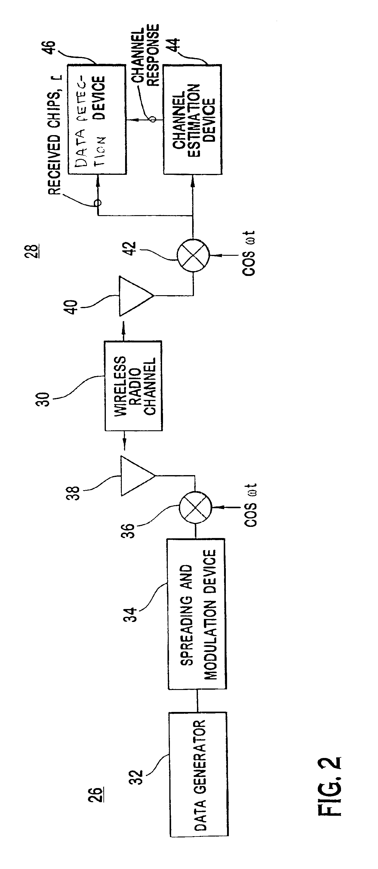
FIG. 2 illustrates a simplified transmitter 26 and receiver 28 using low complexity data detection in a TDD / CDMA communication system. In a typical system, a transmitter 26 is in each UE 141 to 143 and multiple transmitting circuits 26 sending multiple communications are in each base station 121 to 125. The low complexity data detector receiver 28 may be at a base station 121, UEs 141 to 143 or both. The receiver 28 can be used at a UE 141 for either multiuser or single user detection of a medium to high data rate service, such as a 2 megabits per second (Mbs). The receiver 28 can also be used at a base station 121, when only a single UE 141 transmits in a time slot.

The transmitter 26 sends data over a wireless radio channel 30. A data generator 32 in the transmitter 26 generates data to be communicated to the receiver 28. A modulation / spreading sequence insertion device 34 spreads the data and makes the spread reference data time-multiplexed with a midamble training sequence in the...


PUM


Abstract

A time division duplex using code division multiple access user equipment receives a plurality of data signals in a time slot. Each data signal experiences a similar channel response. The user equipment receives a combined signal over the shared spectrum in a time slot. The combined signal comprises the plurality of data signals. The combined signal is sampled at a multiple of a chip rate of the combined signal. The similar channel response is estimated. A channel response matrix or a channel correlation matrix is constructed based on in part the estimated channel response. A spread data vector is determined based on in part a fast fourier transform (FFT) decomposition of a circulant version of the channel response or channel correlation matrix. The spread data vector is despread to recover data from the matrix.

Description

BACKGROUNDThe invention generally relates to wireless communication systems. In particular, the invention relates to data detection in a wireless communication system.FIG. 1 is an illustration of a wireless communication system 10. The communication system 10 has base stations 121 to 125 which communicate with user equipments (UEs) 141 to 143. Each base station 121 has an associated operational area, where it communicates with UEs 141 to 143 in its operational area.In some communication systems, such as code division multiple access (CDMA) and time division duplex using code division multiple access (TDD / CDMA), multiple communications are sent over the same frequency spectrum. These communications are differentiated by their channelization codes. To more efficiently use the frequency spectrum, TDD / CDMA communication systems use repeating frames divided into time slots for communication. A communication sent in such a system will have one or multiple associated codes and time slots a...

Claims


Application Information

Patent Timeline
IPC IPC(8): H04B1/707H04B1/7097H04B7/204H04L5/22H04W88/00
CPCH04B1/71052H04B1/71055H04B1/707
Inventor PAN, JUNG-LINDE, PARTHAPRATIMZEIRA, ARIELA
Owner INTERDIGITAL TECH CORP
Why Eureka
Try Eureka