This helps you quickly interpret patents by identifying the three key elements:
Problems solved by technology
Method used
Benefits of technology
[0013]The improved tab member of the present invention provides an improved solution for a slot and tab closure system. The tab member of the present invention tab portion is a laminate structure with at least one layer in com
Problems solved by technology
While this can result in an effective closure, it often results in misapplication and/or poor alignment of the elements being connected.
Further, hook and loop fasteners can become ineffective due to compression and contamination or can harm surrounding materials.
With an adhesive system, improperly fastening the device may render the entire product unusable.
For example, in diaper applications, repositioning a tape tab which has been fastened improperly may result in tearing the outer cover of the diaper.
Further, adhesive systems are prone to contamination-induced performance problems.
In order to help prevent such problems, the use of these types of fasteners often require inefficient designs and extra material usage which can add to the cost of the products.
Other systems such as buttons, snaps, hooks and eyes, and ties are limited in that they connect discrete points only.
Further, if a span other than a single point needs to be connected, these systems generally require mor
Method used
Image
Click on the blue label to locate the original text in one second.
Reading with bidirectional positioning of images and text.
Examples
second embodiment
[0048]FIG. 17 shows the invention similar to that shown in FIGS. 1-8 where elastic strand structures 41 are provided on the substrate web 2 and / or 9 to provide for an elasticized or elasticizable structure. In a preferred embodiment, the elastic strands are printed onto either web 2 or 9 in accordance with U.S. patent application Ser. No. 10 / 012,698, the substance of which is incorporated herein by reference by its entirety, and produced as show and described in FIG. 20. The applied elastic strands can then be elasticized by suitable permanent deformation or elongation of the substrate webs 2 and / or 9 by any suitable elongation means such as interengaging rolls, external tension or the like. Alternatively, the substrate webs 2 and 9 could be made extensible by suitable methods as described below, or are provided as extensible when coated with the elastic strands.
third embodiment
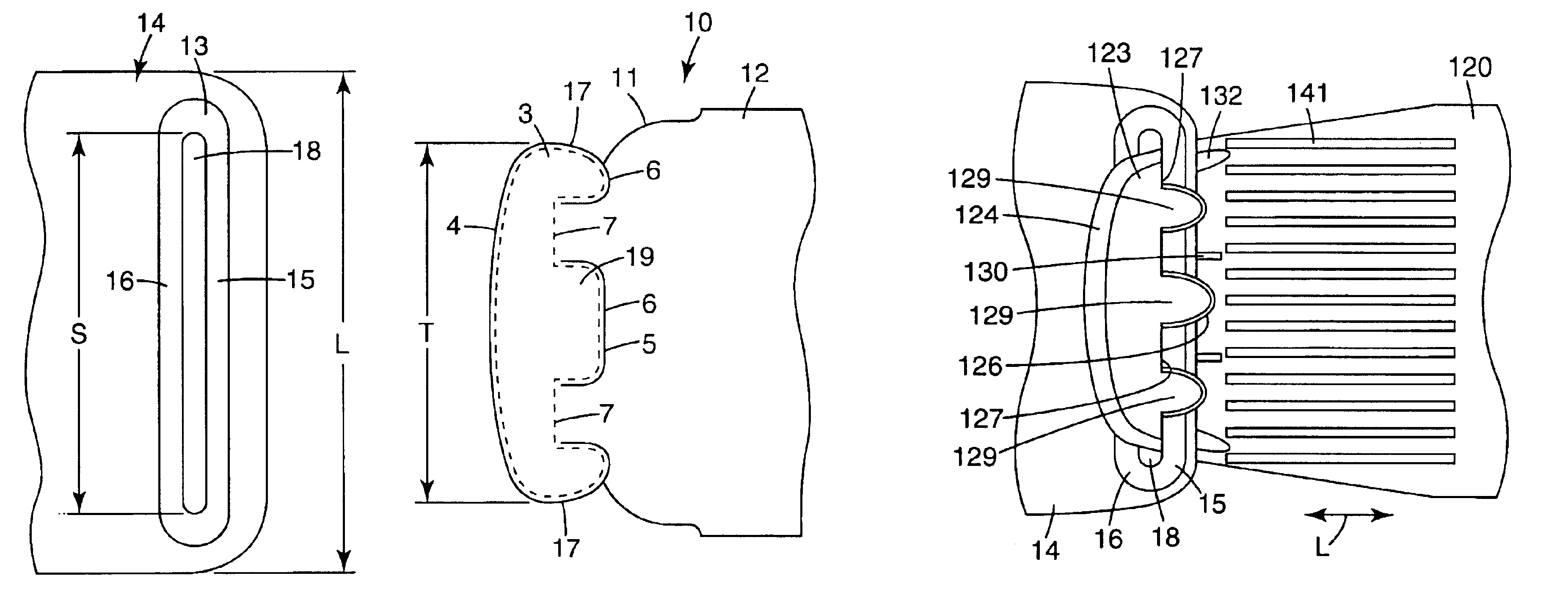
[0049]FIG. 21 shows the invention tab portion structure where a tab substrate 54 is in a form without predefined lip portions and the lip portions 56 are formed by a cutout edge 57. The remaining tab substrate 53 remains integral with the tab carrier substrate 59 where the inner edges of the lip portion cut-outs are preferably provided with a crease or indent 58 to allow the tab to bend or hinge out of the plane of the carrier substrate, for engagement of the lip portions 56 with a corresponding slot.
first embodiment
[0050]FIG. 9 shows an alternative embodiment of a precursor web of the first embodiment tab portion where mirror image tab portions are provided on a single precursor tab portion web 60. As shown in FIG. 9 mating precursor tab portions 63 and 67 are mirror image reflections of each other however they could also be offset or provided at other locations along the lengthwise direction of the completed precursor tab portion web. The center strip 61 can be subsequently removed along the perforated edges 64 and 65, where the continuous lines represent continuous cuts as per the description relative to FIG. 5.
PUM
Property
Measurement
Unit
Length
aaaaa
aaaaa
Fraction
aaaaa
aaaaa
Fraction
aaaaa
aaaaa
Abstract
There is provided an improved tab member for a closure system comprising a tab portion and a slot member. The slot member includes a slit or a loop, with the slot located between an inboard portion and an outboard portion. The tab portion has a tab member having a length, an inner edge, an outer edge and at least one lip portion. The tab member outer edge is passed through the slot of the slot member to engage the fastening device. Once passed through the slot, at least one lip portion of the tab member overlaps or catches the outboard portion of the slot member to prevent the tab member from disengaging from the slot member. The slot member outward portion is retained between the lip portion(s) and the underlying generally flexible tab carrier substrate.
Description
CROSS REFERENCE TO RELATED APPLICATIONS[0001]This is a continuation-in-part of application Ser. No. 10 / 170,619, filed Jun. 13, 2002 abandoned, the disclosure of which is incorporated herein by reference.FIELD OF THE INVENTION[0002]The present invention relates to closure elements for disposable absorbent articles such as diapers, training pants and incontinence pads. More particularly, the present invention relates to closure elements for disposable absorbent articles which are easy to use and manufacture.BACKGROUND OF THE INVENTION[0003]Many different types of refastenable closures elements are known, including ties, pins, hook and loop systems, hook and eye systems, buttons, snaps, interlocking shapes, buckles, adhesive tapes, cohesive surfaces, and zippers and other slide connectors. Such fasteners have been used on a variety of products, both durable and disposable. Typical uses include envelopes, clothing, diapers, packages, footwear, construction closures, general attachment n...
Claims
Application Information
Patent Timeline
Application Date:The date an application was filed.
Publication Date:The date a patent or application was officially published.
First Publication Date:The earliest publication date of a patent with the same application number.
Issue Date:Publication date of the patent grant document.
PCT Entry Date:The Entry date of PCT National Phase.
Estimated Expiry Date:The statutory expiry date of a patent right according to the Patent Law, and it is the longest term of protection that the patent right can achieve without the termination of the patent right due to other reasons(Term extension factor has been taken into account ).
Invalid Date:Actual expiry date is based on effective date or publication date of legal transaction data of invalid patent.