Combustion system for a heater

a combustion system and heater technology, applied in the field of heaters, can solve the problems of not being able to adjust the input gas flow rate without affecting safe and efficient combustion, and achieve the effect of reducing the heat output of the heater and reducing the risk of fir

Inactive Publication Date: 2005-04-19
SUNBELT RENTALS INC
View PDF30 Cites 46 Cited by
  • Summary
  • Abstract
  • Description
  • Claims
  • Application Information

AI Technical Summary

Problems solved by technology

However, one thing previous burner assemblies in other heaters have in common is that they are not capable of having their input gas flow rate adjusted without affecting safe and efficient combustion.

Method used


Image

  • Combustion system for a heater
  • Combustion system for a heater
  • Combustion system for a heater

Examples


Embodiment Construction

[0025]In describing preferred embodiments of the invention, specific terminology will be selected for the sake of clarity. However, the invention is not intended to be limited to the specific terms so selected, and it is to be understood that each specific term includes all technical equivalents that operate in a similar manner to accomplish a similar purpose.

[0026]The terms “right,”“left,”“top,” and “bottom” designate relative directions in the drawings to which reference is made. The terms “inner” and “outer” will be used to refer to a general area inside or outside of the heater.

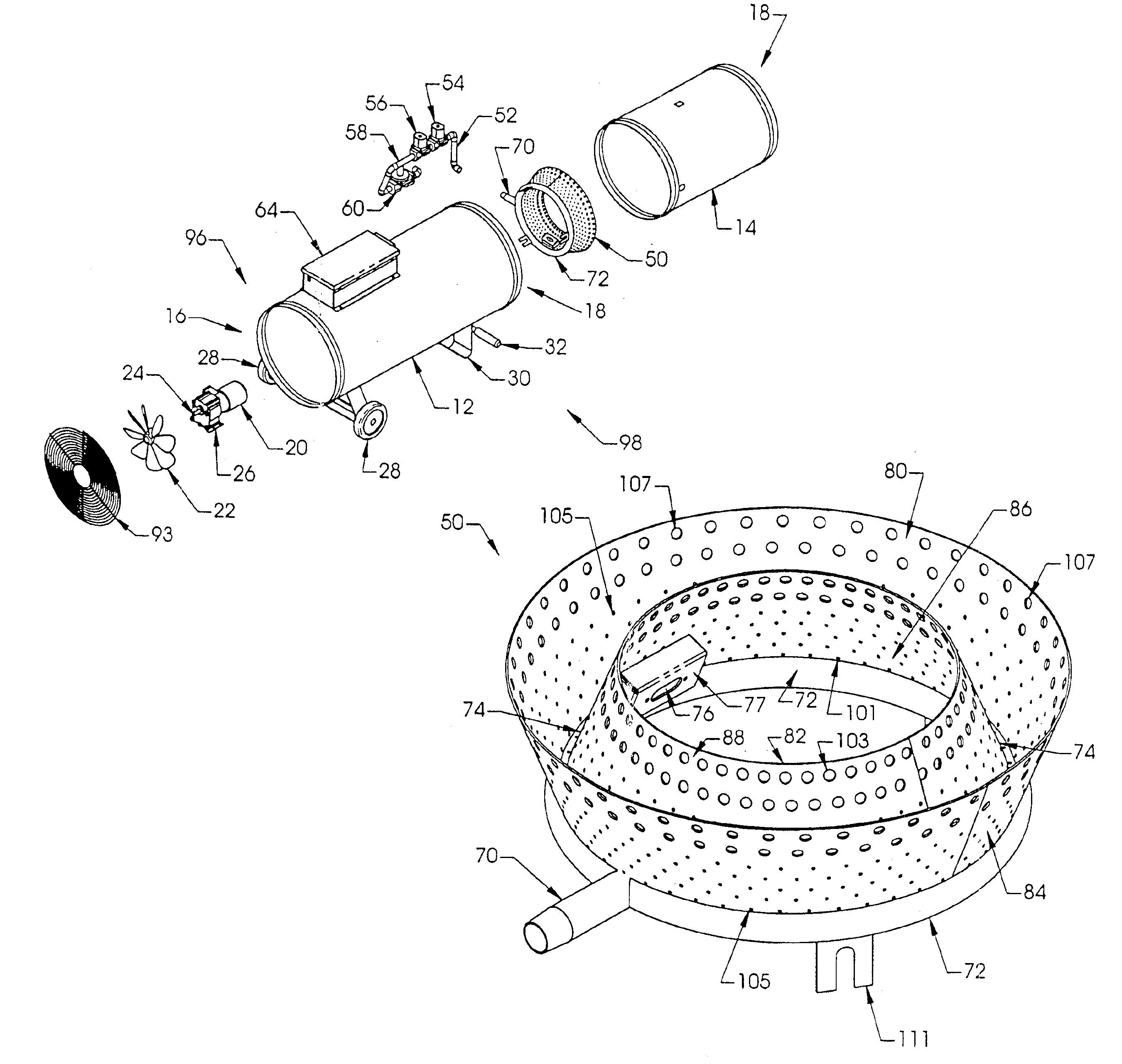
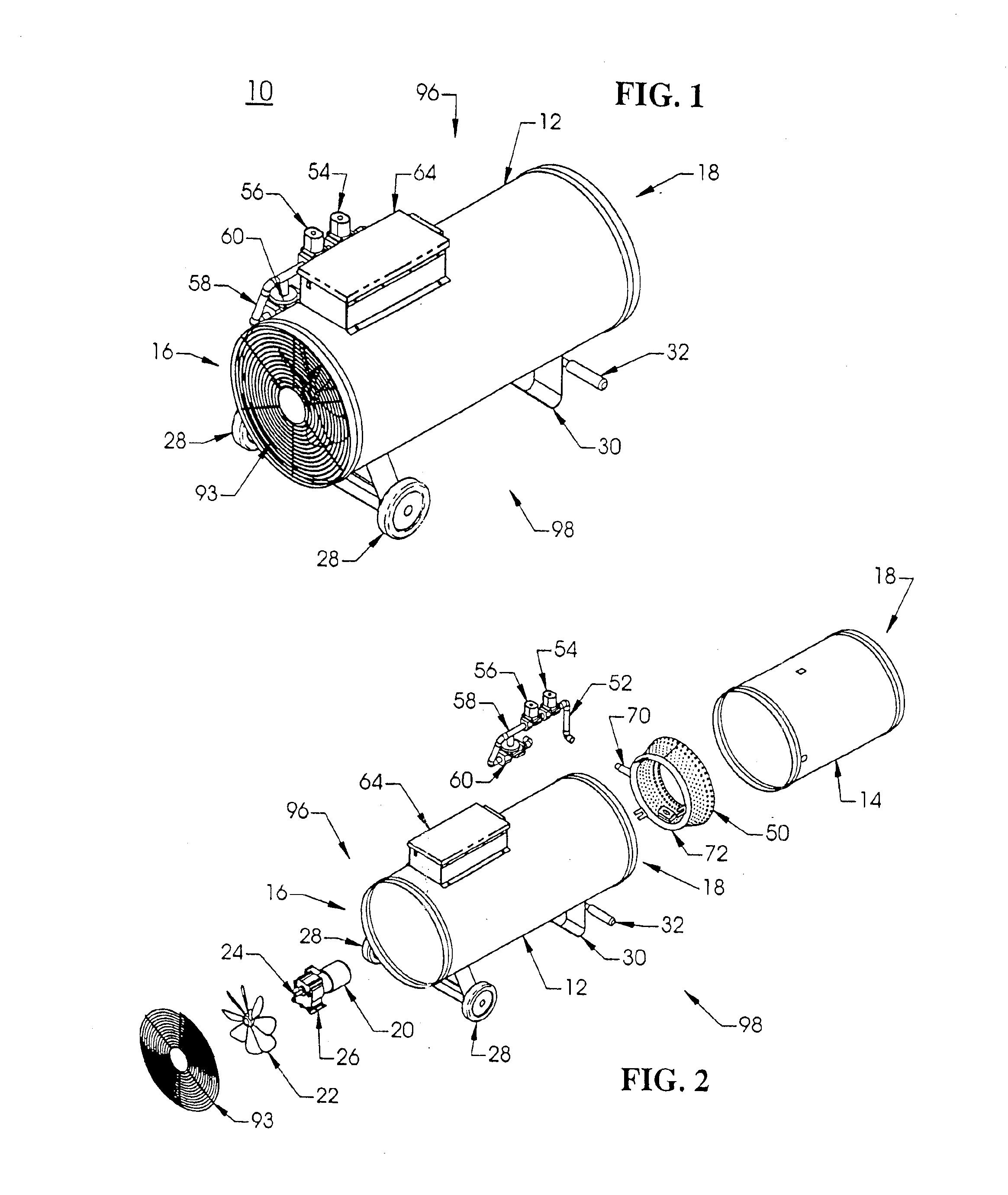
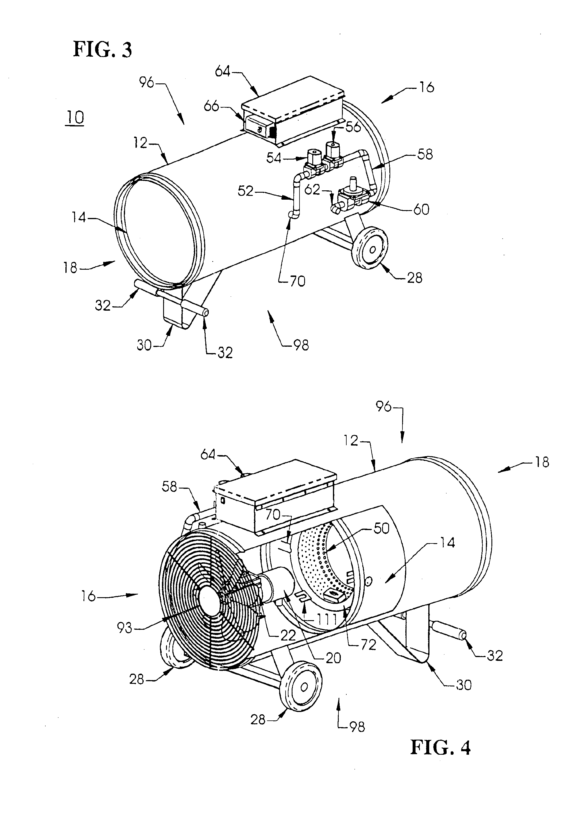
[0027]The preferred embodiments of the present invention will now be described in detail with reference to the accompanying drawings in which a forced-air or direct-fired heater in accordance with the present invention is generally indicated at 10.

[0028]Referring to FIG. 1, the forced-air heater 10 includes an elongated, substantially cylindrical housing 12. Although the cylindrical housing 12 may be form...


PUM


Abstract

A combustion system for a portable forced air heater having two frusta-conical sections attached to a circular burner tube, wherein each frusta-conical section has pre-determined vent hole patterns that allow the gas heater to have a variable burn rate.

Description

FIELD OF THE INVENTION[0001]The present invention relates generally to heaters and, in particular, a new combustion system for use in a forced-air type heater.BACKGROUND OF THE INVENTION[0002]Portable heaters are well known. One type of portable heater for commercial use draws air into the heater and forces the air through a flame. As the air passes through the flame, it is heated and output into a room or other structure which is intended to be heated. This type of portable heater is referred to as a forced-air and / or direct-fired heater. In a direct-fired heater, part of the product of the combustion is output into the room or the structure to be heated.[0003]Direct-fired heaters are fairly distinctive in their appearance since they utilize an elongated cylindrical housing. Within the housing is mounted a means for moving the air (usually at a high velocity) and a combustion system.[0004]The means for moving the air consists of a fan (or a propeller) attached to an electric motor....

Claims


Application Information

Patent Timeline
Patent Type & Authority Patents(United States)
IPC IPC(8): F23D14/00
CPCF23D14/00F23D2900/21003
Inventor TOPP, DANIEL P.
Owner SUNBELT RENTALS INC
Why Eureka
Try Eureka