Structure for isolating mounting and clamping forces of a power clamp

a technology of power clamps and structures, which is applied in the field of power clamps, can solve the problems of creating extra loads on the manipulators to which the housing is attached, the design still has the disadvantage of having all the planar plates fabricated from high strength steel

Inactive Publication Date: 2005-04-19
NORGREN AUTOMOTIVE
View PDF7 Cites 18 Cited by
  • Summary
  • Abstract
  • Description
  • Claims
  • Application Information

AI Technical Summary

Problems solved by technology

The open design of the body allows entry of dirt and / or other foreign matter into the interior of the body which can create problems with the internal working mechanisms of the power-operated clamp.
Due to the nature of these materials, as well as the tolerances and the enclosed configurations required of an enclosed power clamp housing, enclosed power clamps are rather difficult and expensive to manufacture, especially power clamp housings.
In addition, these metals tend to be relatively heavy, thereby creating extra loads on the manipulators on which the housings are attached.
These types of designs still have the disadvantage of having all of the planar plates fabricated from a high strength steel.
In addition, such designs have the design and manufacturing concerns of having to stack and connect a plurality of planar plates to create a power clamp.

Method used


Image

  • Structure for isolating mounting and clamping forces of a power clamp
  • Structure for isolating mounting and clamping forces of a power clamp
  • Structure for isolating mounting and clamping forces of a power clamp

Examples


Embodiment Construction

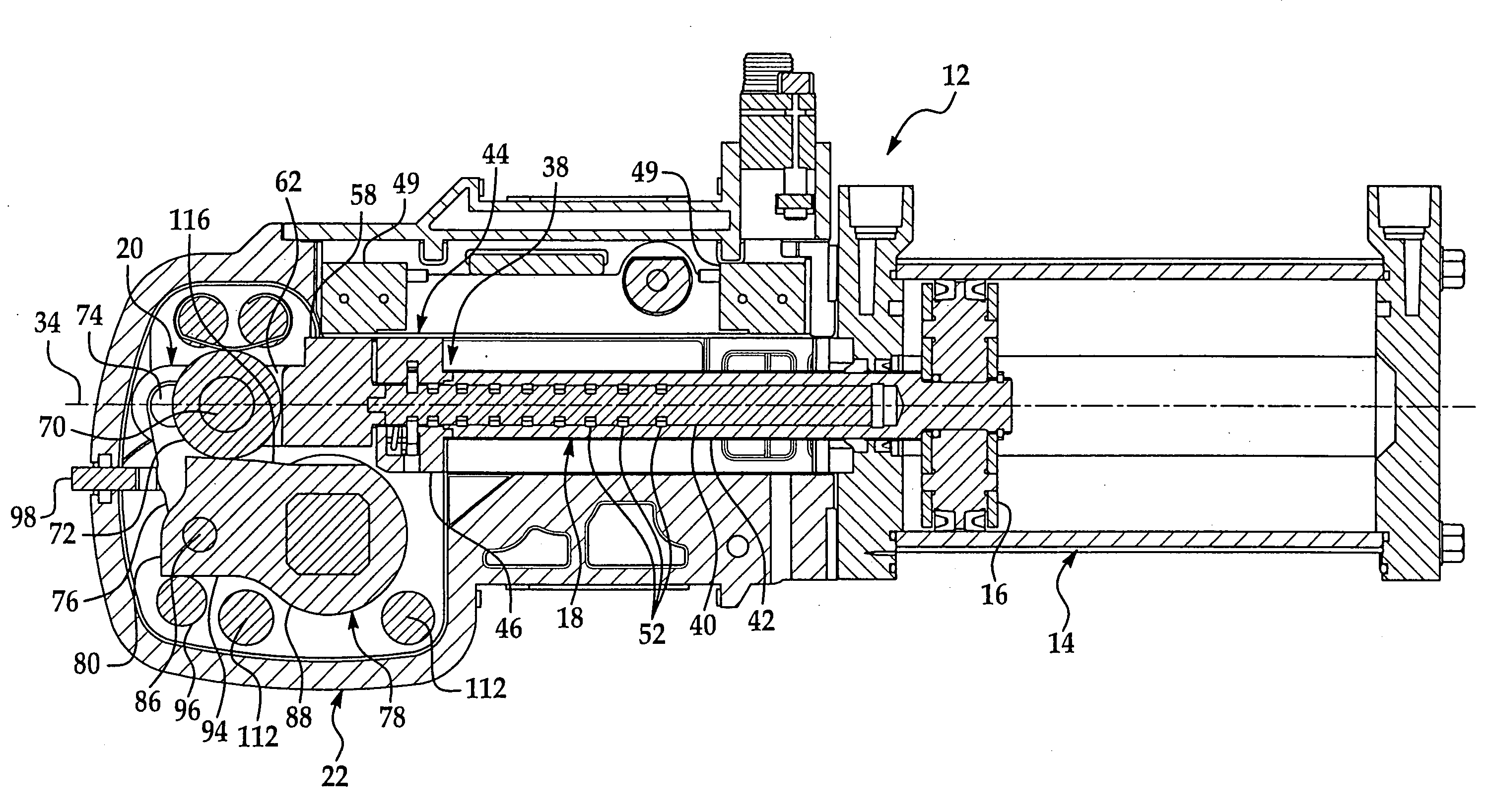
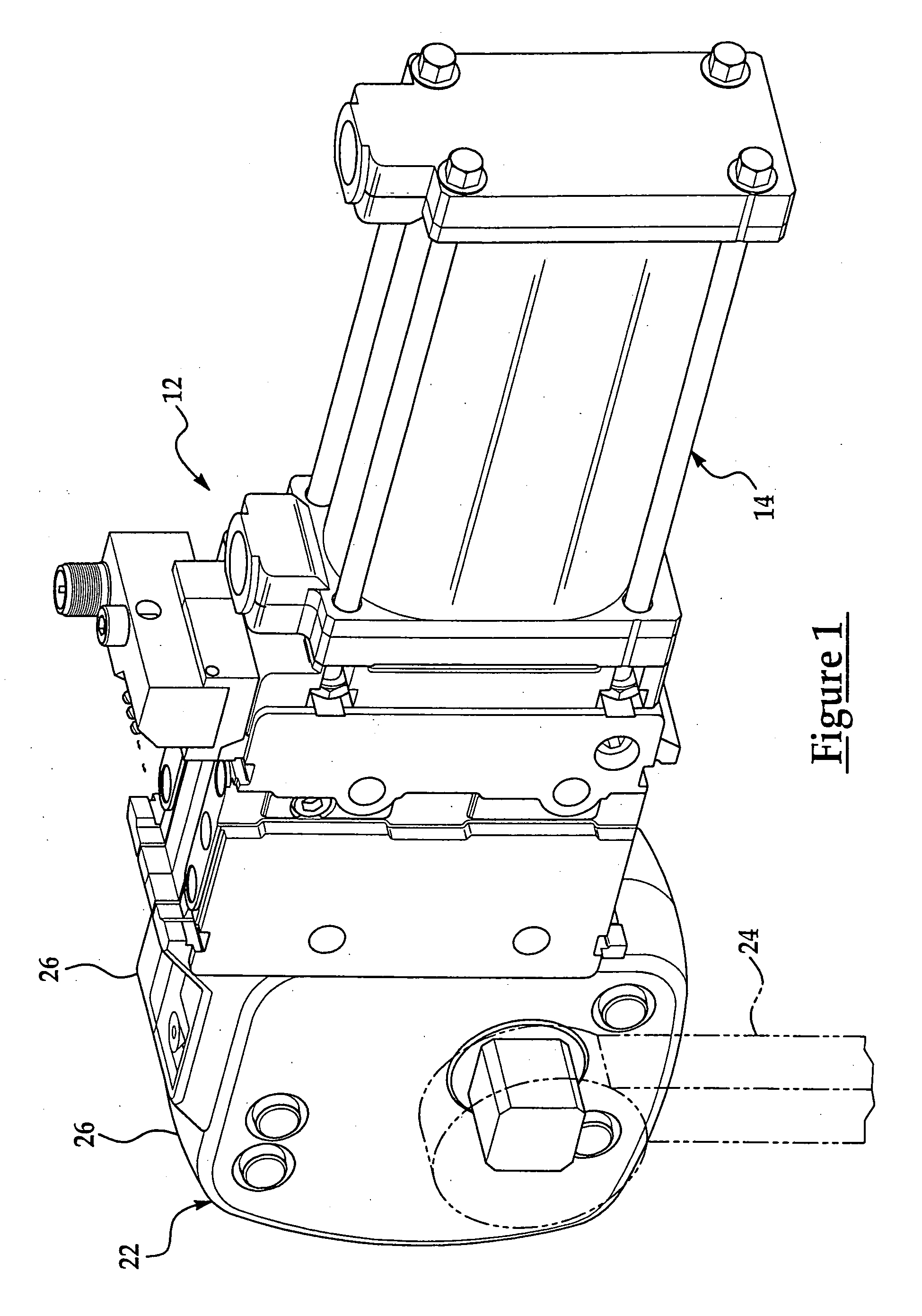
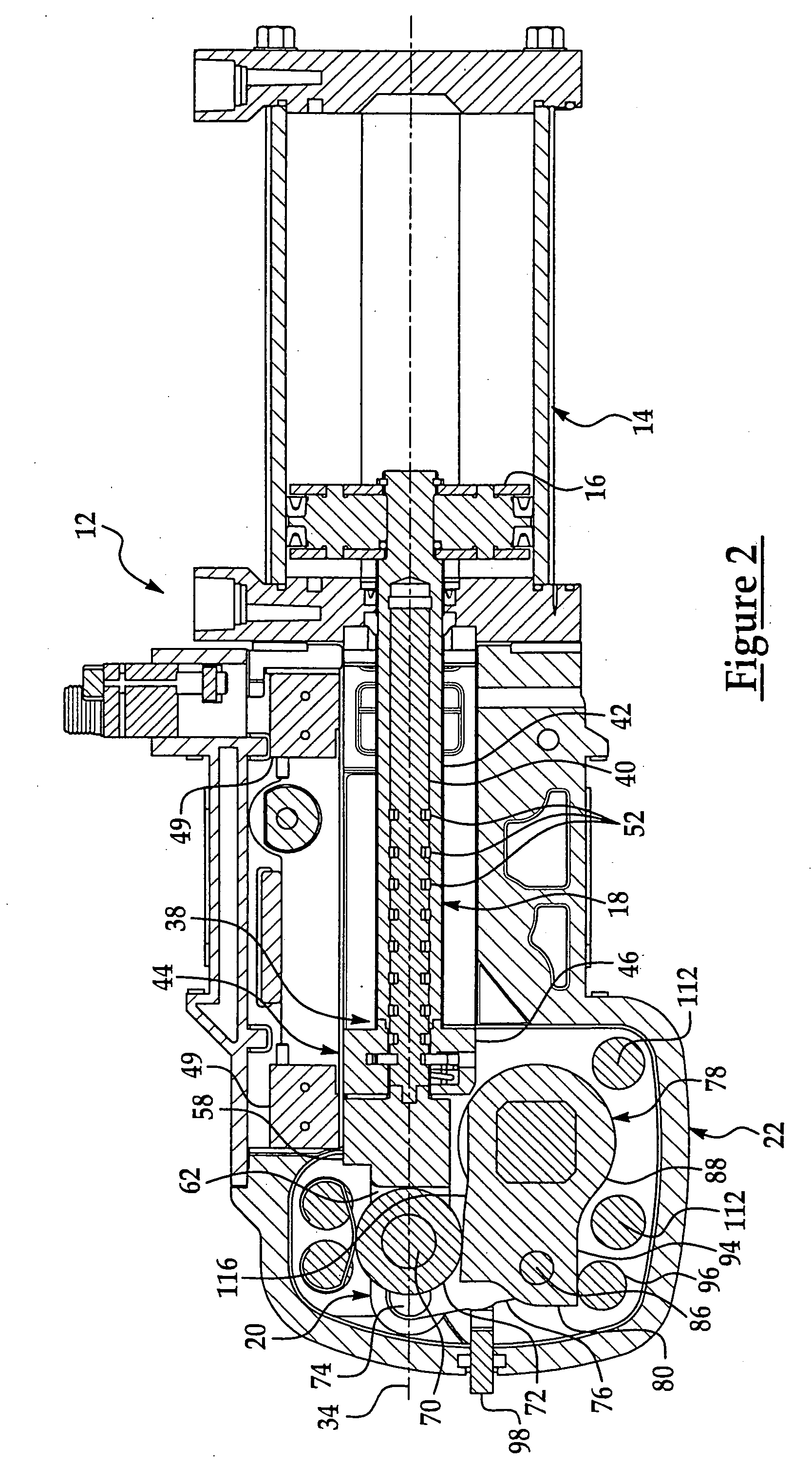
[0019]FIGS. 1–3 illustrate a plate and beam structure 10 of a power clamp 12 as defined by the present invention. The power clamp 12 is actuated by a fluid cylinder or linear actuator 14, preferably pneumatic or hydraulic. The linear actuator 14 includes a piston 16 attached to the end of a piston rod 18. The linear actuator 14 provides linear reciprocal movement to the piston rod 18 which, in turn, is coupled to a linkage assembly 20 of the power clamp 12. The linkage assembly 20 is disposed within a housing 22 of the power clamp 12 and converts the linear motion of the piston rod 18 into rotary motion of a clamp arm 24 between a clamped position and an unclamped position.

[0020]The housing 22 of the power clamp 12 includes two bilateral halves 26 that form an enclosed, hollow portion having the plate and beam structure 10 disposed therein. One end of the housing 22 is connected to the linear actuator 14 and open to receive the free end of the piston rod 18. The plate and beam struc...


PUM


Abstract

An apparatus for absorbing the mounting and clamping forces of a linkage assembly of a power clamp. An enclosed bilateral housing of a power clamp is provided, wherein a linear actuator is connected to the housing and provides a piston rod extending into the housing. A linkage assembly is connected to the piston rod and disposed within the housing for converting the linear motion of the piston rod into rotary motion of a clamp arm. A high strength plate and beam structure is disposed within the housing and connected to the linkage assembly for absorbing the mounting and clamping forces generated by the linkage assembly. By absorbing the mounting and clamping forces of the linkage assembly, the high strength plate and beam structure allows the housing to be fabricated from a lightweight, inexpensive material.

Description

CROSS-REFERENCE TO RELATED APPLICATION[0001]This application claims the benefit of the filing dates of U.S. Provisional Patent Application Ser. No. 60 / 225,974, filed Aug. 17, 2000, and U.S. Provisional Patent Application Ser. No. 60 / 238,902, filed Oct. 10, 2000.FIELD OF THE INVENTION[0002]The field of the invention relates to power clamps, and more particularly, to an apparatus and method for absorbing the excessive clamping forces produced by the power clamp.BACKGROUND OF THE INVENTION[0003]Power clamps are known of the type in which linear actuating reciprocating movement of a fluid motor is adapted to be translated into rotary movement of a clamp arm. The clamp arm is attached to a linkage assembly or other force transmitting means which in turn is connected to the end of a piston rod of the fluid motor. In the retracted position of the fluid motor, the clamp arm is normally in a released position, that is, the clamp arm is removed from a work supporting surface. When the fluid m...

Claims


Application Information

Patent Timeline
Patent Type & Authority Patents(United States)
IPC IPC(8): B25B5/00B25B5/16B25B5/12
CPCB25B5/16B25B5/122
Inventor WHEELER, TIMOTHYDELLACH, JEFFREYMORRONEY, WAYNE
Owner NORGREN AUTOMOTIVE
Why Eureka
Try Eureka