Liquid ejecting device

Inactive Publication Date: 2005-04-19
SEIKO EPSON CORP
View PDF3 Cites 11 Cited by
  • Summary
  • Abstract
  • Description
  • Claims
  • Application Information

AI Technical Summary

Benefits of technology

[0036]Preferably, a liquid ejection amount in the first flushing mode of the high flushing mode is larger than that in the flushing modes other than the high flushing mode. In the above configuration, a time taken for the flushing mode performed for each operation job in the high flushing mode and an amount of waste liquid are larger than those in other flushing modes. In this respect, the effect to reduce the liquid ejection amounts in the second and subsequent flushing modes is remarkable. A flushing mode is performed by the liquid ejection of an liquid ejection amount suitable for a property change degree. In particular, the flushing mode is performed by use of the ejection liquid whose amount is increased as the result of removing the liquid having the highest property change degree. A more exact recovering operation is performed at and near the nozzle orifices.
[0037]Preferably, the liquid is an ink for printing and is used for an ink jet recording device. The flushing mode is applied to a property change of the ink, so that a normal ink ejection is secured and a good print quality is ensured. Further, a small space

Problems solved by technology

As a result, an unsatisfactory damping effect is frequently obtained.
As a result, when the ink jet recording device is operated again, the ink drop ejection is improper.
In a state that the viscosity of the ink is increased, some troubles tend to occur.
For example, the printing operation cannot start quickly or a print quality is deteriorated.
In the case of the nozzle orifices 2, which are located, for example, at the upper and lower ends of the nozzle array, and have each an extremely small

Method used


Image

  • Liquid ejecting device
  • Liquid ejecting device
  • Liquid ejecting device

Examples


Embodiment Construction

[0047]An embodiment of the present invention will be described in detail with reference to the accompanying drawings.

[0048]A liquid ejecting device of the invention is operable to eject any of various kinds of liquids, as described above. In an illustrated embodiment, the liquid ejecting device is typically applied to an ink jet recording device.

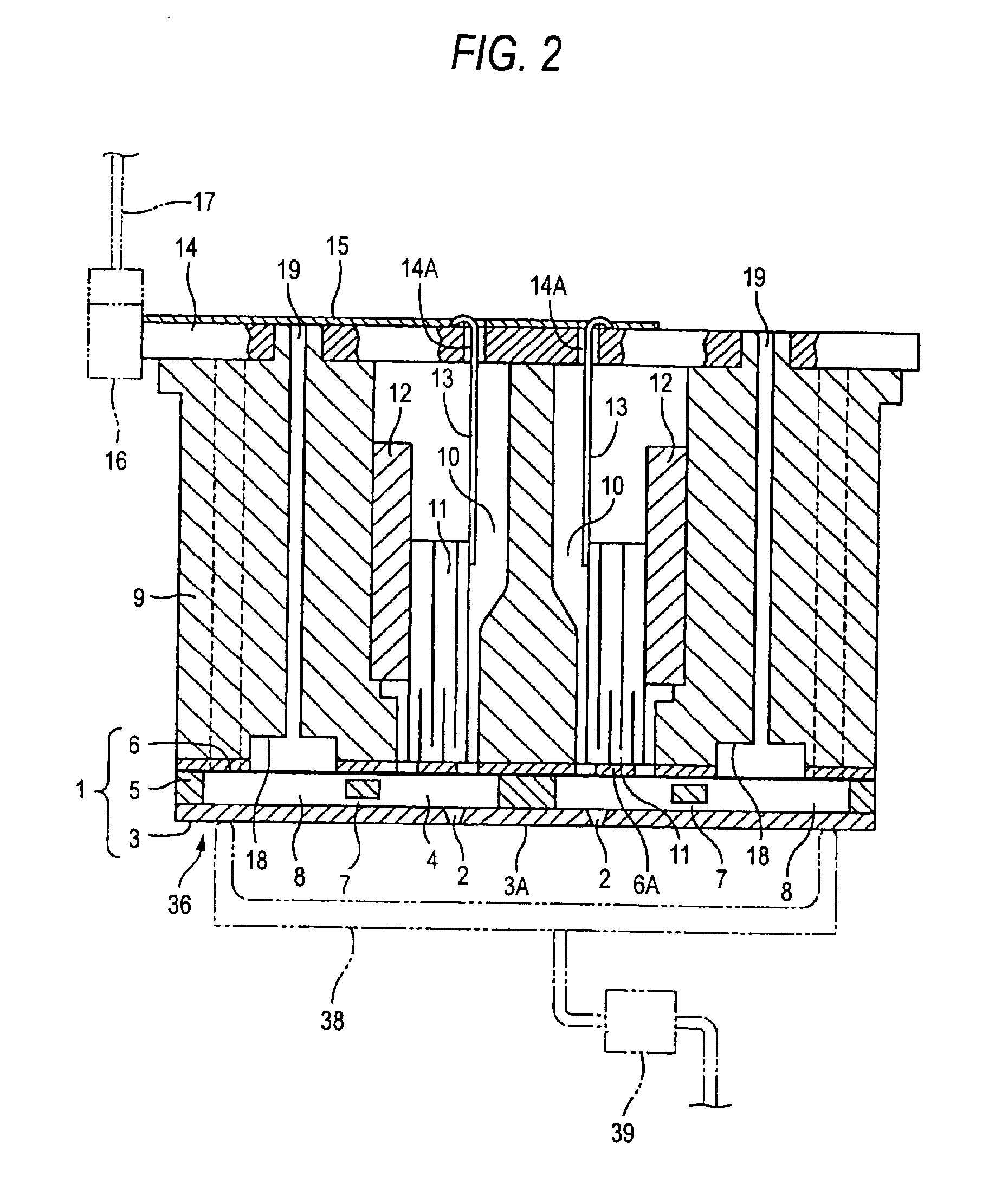
[0049]FIG. 1 is a perspective view showing a peripheral structure of an ink jet recording device according to the present invention. FIG. 2 is a cross sectional view showing a recording head 36, which is similar to the recording head H already described referring to FIG. 6. In FIG. 6, like or equivalent portions are designated by like reference numerals used in FIG. 2.

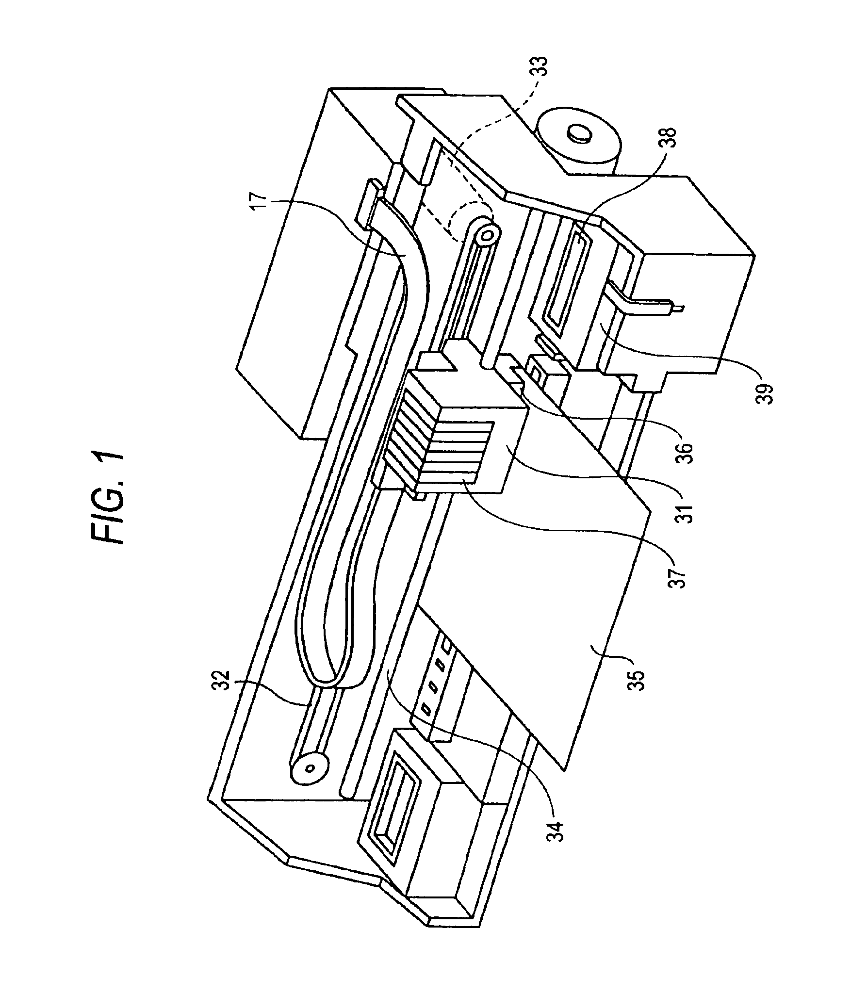
[0050]The ink jet recording device includes a carriage 31 and a capping device 38. The carriage 31 includes six ink cartridges 37 mounted in an upper part thereof, and a recording head 36 mounted on a lower surface thereof. The capping device 38 is provided for sealing the reco...


PUM


Abstract

A liquid ejecting device includes a liquid ejecting head which has a nozzle formation face on which nozzle orifices for ejecting liquid drops are formed and a controller which performs a recovery operation for removing a liquid having a changed liquid property. The recovery operation is performed by using at least a flushing mode in which liquid drops are ejected in a state that the nozzle formation face is sealed. The controller selectively performs a plurality of flushing modes which are set in accordance with degrees in change of a liquid property of the liquid drops being at and near the nozzle orifices. The degrees in change of the liquid property of the liquid drops are determined by a relation between an accumulative time that the nozzle orifices are left in a sealing state and an accumulative time that a liquid ejection is executed. A high flushing mode of the flushing modes for removing the liquid having a high degree in change of the liquid property has a first flushing mode which is performed at a first time and second and subsequent flushing modes which is performed at a second and subsequent time. The number of liquid drops ejected in the first flushing mode is greater than the number of liquid drops ejected in the second and sequent flushing modes.

Description

BACKGROUND OF THE INVENTION[0001]The present invention relates to a liquid ejecting device which ejects a liquid pressurized in a pressure generating chamber in the form of liquid drops through nozzle orifices.[0002]There is known a liquid ejecting device of the type which ejects a liquid pressurized in a pressure generating chamber in the form of liquid drops through nozzle orifices, and the liquid ejecting device is capable of ejecting any of various kinds of liquids. A typical example of such a liquid ejecting device is a recording head used in an ink jet recording device. A related technique will be described by using the recording head of the ink jet recording device, and with reference to FIGS. 6 and 7.[0003]The recording head includes a flow passage unit 1 having nozzle orifices 2 and a head case 9 in which the flow passage unit 1 is attached thereto by bonding.[0004]The flow passage unit 1 is formed with a nozzle plate 3, a passage substrate 5 and a vibration plate 6, which ...

Claims


Application Information

Patent Timeline
IPC IPC(8): B41J2/165B41J2/175
CPCB41J2/1652
Inventor SUZUKI, KAZUNAGA
Owner SEIKO EPSON CORP
Why Eureka
Try Eureka