Fuel cell system power control method and system

a fuel cell and power control technology, applied in the field of power generation, can solve problems such as shortened battery life, and achieve the effect of reducing the cost and size of the fuel cell power conditioning system

Inactive Publication Date: 2005-04-19
ABB (SCHWEIZ) AG
View PDF18 Cites 53 Cited by
  • Summary
  • Abstract
  • Description
  • Claims
  • Application Information

AI Technical Summary

Benefits of technology

[0008]In an exemplary embodiment of the present invention, a fuel cell or fuel cell stack is placed in parallel with a battery via a switch. The voltage on the output of the fuel cell, or stack, is held nearly constant by the battery and the power flow is controlled by adjusting the fuel cell operating parameters (such as temperature or air flow) and by opening and closing the switch. The

Problems solved by technology

The prior art either slams the battery at high charge and discharge rates (thus causing sh

Method used


Image

  • Fuel cell system power control method and system
  • Fuel cell system power control method and system
  • Fuel cell system power control method and system

Examples


Embodiment Construction

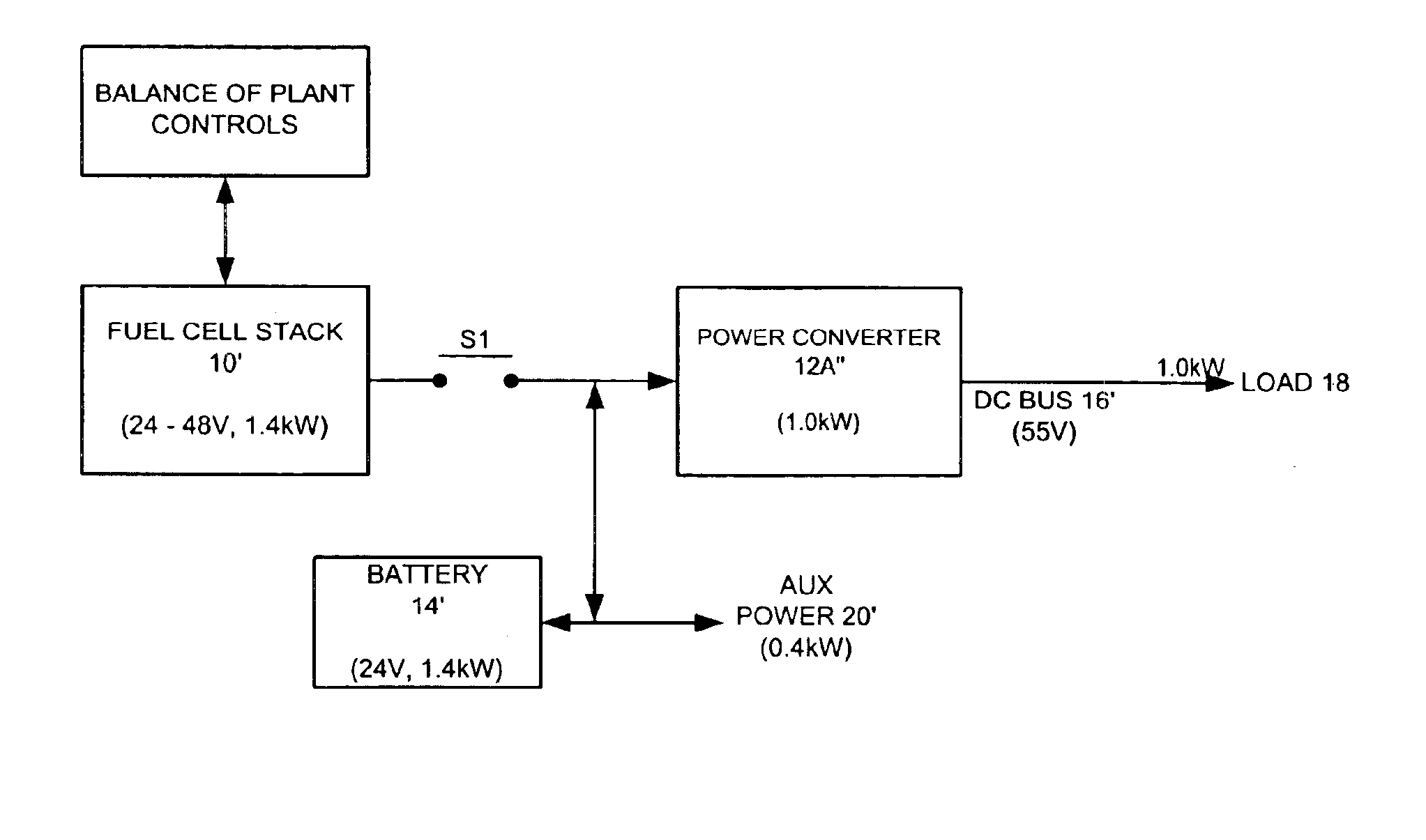
[0016]FIG. 4 depicts a presently preferred embodiment of the invention. In this embodiment, a fuel cell stack 10′ is placed directly in parallel with an energy storage device 14′ (e.g., a battery or capacitor) through a switch S1. The steady-state power flow from the fuel cell stack is controlled, using BOP controls (see BOP controller in FIG. 4), by adjusting the fuel cell operating conditions such as temperature, air flow, fuel flow, air pressure or fuel pressure. The transient power flow comes from the storage device 14′. For example, when the load 18′ suddenly increases, the energy storage device will provide power to meet the increase. The fuel cell operating conditions will then be adjusted to provide more power from the fuel cell stack 10′. As the fuel cell power increases, the output power from the energy storage device decreases. When the load 18 suddenly decreases, the fuel cell stack 10′ will be producing more power than required by the load. The extra power will flow int...


PUM


Abstract

A fuel cell is placed in parallel with a battery via a mechanical switch. The voltage is held nearly constant by the battery and the power flow is controlled by adjusting the fuel cell operating parameters (such as temperature or air flow) and by opening and closing the mechanical switch. The result is a system that operates at nearly constant voltage without the need for an expensive power conditioning system. The output of the system can then be processed via a traditional power conditioning system such as an inverter or dc-to-dc converter without the need for a wide range of input operating voltages. This reduces the cost and size of the fuel cell power conditioning system.

Description

FIELD OF THE INVENTION[0001]The present invention relates generally to the field of power generation, and more particularly to an improved fuel cell-based power conversion system.BACKGROUND OF THE INVENTION[0002]FIG. 1 shows a block diagram of a power conversion system that can be used with a fuel cell stack 10. Since the fuel source normally cannot keep up with load transients, it is often necessary to include, in addition to a power conditioner 12A, a battery 14 or other energy storage device to provide power during load transients. FIG. 1 shows a switch S1 used to disconnect the fuel cell stack from the system. Switch S1 may also be used to prevent reverse flow of current into the stack. Power conditioner 12A processes the power from the fuel cell stack 10 to a common dc bus 16. Power conditioner 12A must operate over a large range of input voltage since the fuel cell stack voltage changes significantly with load. A second power conditioner 12B controls the flow of power between ...

Claims


Application Information

Patent Timeline
IPC IPC(8): H02J9/00H01M16/00H01M8/04H02J7/34
CPCH01M16/003H01M8/0494H01M8/04007H01M8/04082H01M8/04701H01M8/04753H01M8/04798Y02E60/50H01M2250/402H02J7/34Y02B90/12Y02B90/10
Inventor JUNGREIS, AARON M.
Owner ABB (SCHWEIZ) AG
Why Eureka
Try Eureka