Electron accelerator having a wide electron beam

a technology of electron beam and electron beam, which is applied in the direction of ion beam tubes, machines/engines, nuclear engineering, etc., can solve the problem that the system can require a relatively large amount of spa

Inactive Publication Date: 2005-04-19
HITACHI ZOSEN CORP
View PDF40 Cites 18 Cited by
  • Summary
  • Abstract
  • Description
  • Claims
  • Application Information

AI Technical Summary

Benefits of technology

[0006]In preferred embodiments, the exit window has a second end region opposite to the first end region. Electrons passing through the exit window at the second end region are angled outwardly. At least a portion of the electrons angled outwardly through the second end region are directed beyond the outer perimeter. The electron generator is positioned within the vacuum chamber relative to the exit window in a manner to form flat electrical field lines near the central region of the exit window and curved electrical field lines near the first and second end regions of the exit window. The flat electrical field lines direct electrons through the central region in a perpendicular relation to the exit window and the curved electrical field lines direct electrons through the first and second end regions at outward angles. The exit window has window openings for allowing passage of electrons therethrough. The window openings near the first and second end regions of the exit window are angled outwardly for facilitating the passage of outwardly angled electrons. In this manner, the present invention electron accelerator is able to generate an electron beam that is wider than the width of the accelerator.
[0012]In another embodiment, a system is adapted for irradiating a continuously moving web. The web travels from a pair of upstream pinch rollers to a downstream roller. The system includes an electron accelerator system for irradiating the web with an electron beam. An enclosure substantially encloses the web between the up stream pinch rollers and the downstream roller. The enclosure has an up st ream shield positioned close to the upstream pinch rollers and a downstream shield positioned close the downstream roller. An inert gas source is coupled to the enclosure to fill the enclosure with inert gas. The upstream and downstream shields are positioned sufficiently close to the upstream pinch rollers and downstream roller to prevent substantial inert gas from escaping the enclosure. The upstream pinch rollers block air from the web as the web enters the enclosure such that substantial intrusion of air into the enclosure is prevented.
[0014]In still another embodiment, a system is adapted for irradiating a continuously moving web. An electron accelerator irradiates the web with an electron beam. An enclosure encloses the electron accelerator and a portion of the web. A series of ultrasonic members are positioned within the enclosure. The web travels over the ultrasonic members and is redirected within the enclosure. The enclosure has an entrance and an exit for the web which are out of direct alignment with the electron accelerator to prevent the escape of radiation from the enclosure.

Problems solved by technology

A drawback of an electron beam system having staggered electron beam devices is that such a system can require a relatively large amount of space, particularly in situations where multiple sets of staggered electron beam devices are positioned in series along the direction of the moving web for curing coatings on webs moving at extremely high speeds (up to 3000 ft. / min.).
This can be a problem in space constrained situations.

Method used


Image

  • Electron accelerator having a wide electron beam
  • Electron accelerator having a wide electron beam
  • Electron accelerator having a wide electron beam

Examples


Embodiment Construction

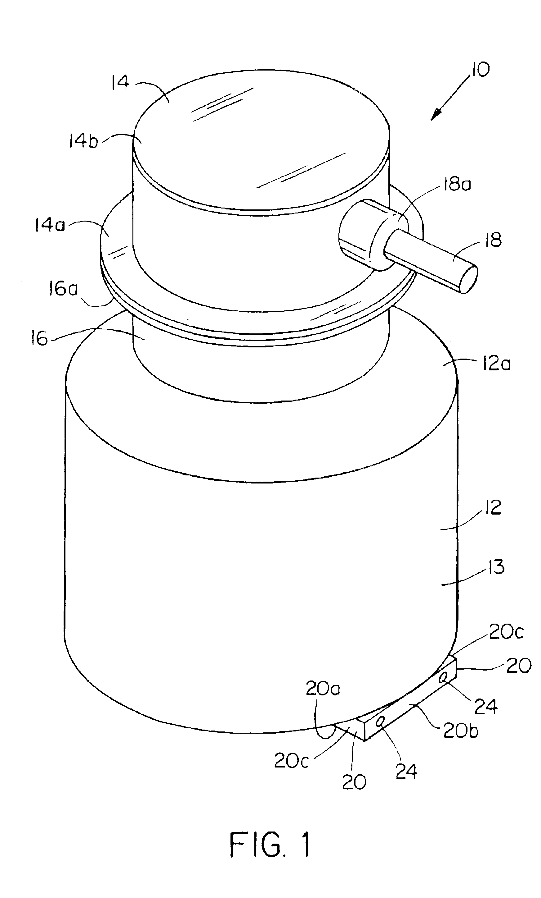
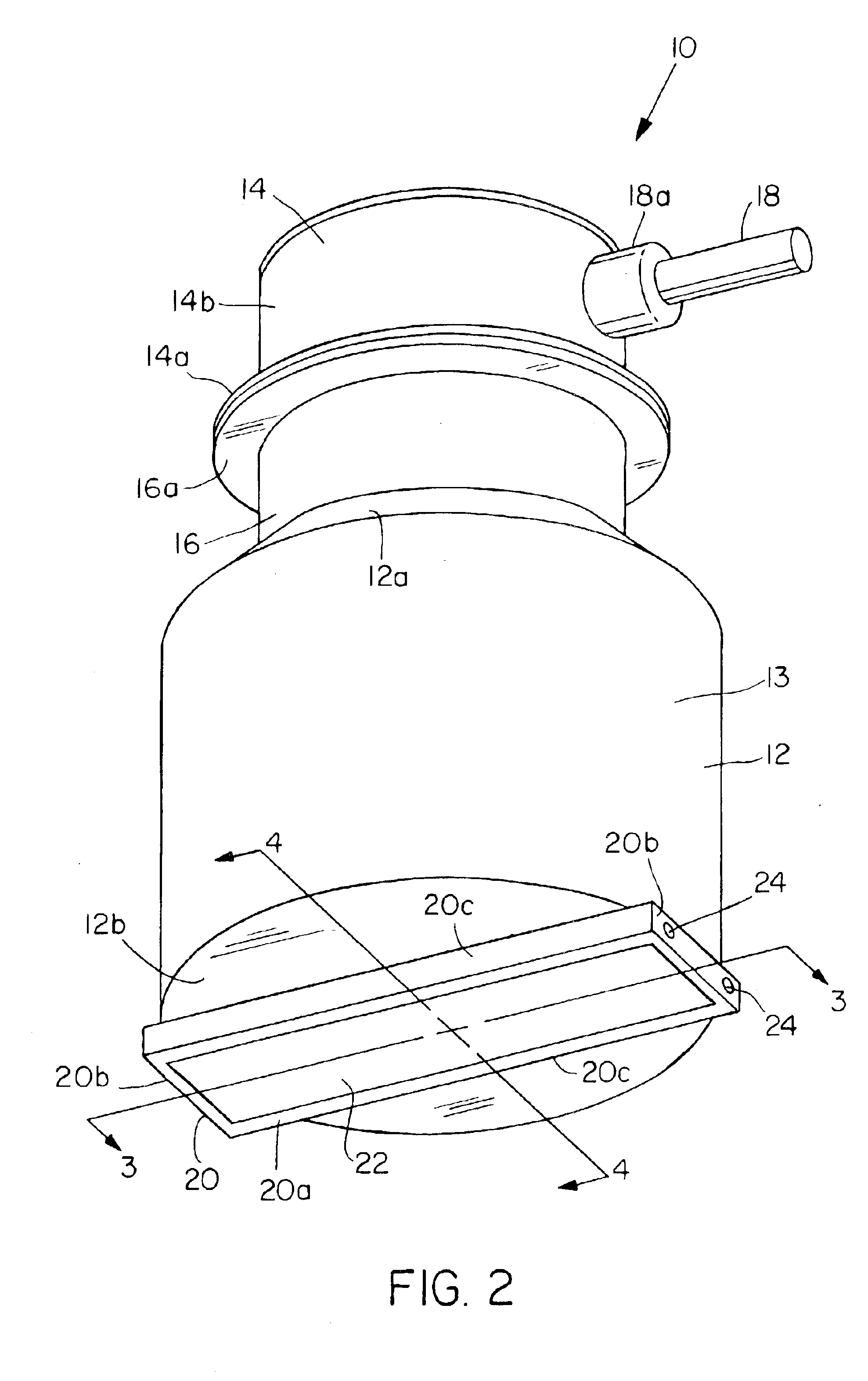
[0035]Referring to FIGS. 1-5, the present invention provides an electron beam accelerator device 10 which produces an electron beam 68 (FIG. 5) having portions that extend laterally beyond the sidewalls 13 of electron beam device 10. In other words, electron beam 68 is wider than electron beam device 10. Electron beam device 10 includes a hermetically sealed generally cylindrical vacuum chamber 12 having a permanent vacuum therein and a high voltage connector 14 coupled to the vacuum chamber 12. An electron gun 40 (FIGS. 3, 4, and 5) is positioned within the interior 48 of vacuum chamber 12 and includes a generally disc shaped or circular filament housing 42 containing a pair of filaments 44 for generating electrons 60 (FIG. 5). The electrons 60 generated by filaments 44 are accelerated from electron gun 40 out through an exit window 20 extending from the bottom 12b of vacuum chamber 12 in an electron beam 68.

[0036]Exit window 20 includes a rectangular support plate 20a having a ser...


PUM


Abstract

An electron accelerator for generating an electron beam includes a vacuum chamber having an outer perimeter and an electron beam exit window. The exit window has a central region and a first end region. An electron generator is positioned within the vacuum chamber for generating electrons. The electron generator and the vacuum chamber are shaped and positioned relative to each other to accelerate the electrons in an electron beam out through the exit window. The electrons pass through the central region of the exit window substantially perpendicular to the exit window and through the first end region of the exit window angled outwardly relative to the exit window. At least a portion of the outwardly angled electrons are directed beyond the perimeter of the electron accelerator.

Description

RELATED APPLICATION[0001]This application is a divisional of U.S. application Ser. No. 09 / 209,024, filed Dec. 10, 1998 now U.S. Pat. No. 6,545,398. The entire teachings of the above application are incorporated herein by reference.BACKGROUND[0002]During manufacturing, paper goods often have some form of coating applied thereon such as adhesives or inks which usually require some type of curing process. Examples of such coated paper goods include magazines, labels, stickers, prints, etc. The coatings are typically applied to the paper when the paper is in the form of a continuously moving web of paper. Current manufacturing methods of curing coatings on a moving web include subjecting the coatings to heat, UV light or electron beams.[0003]When curing coatings on a moving web with electron beams, an electron beam system is usually positioned over the moving web. If the web has a large width, for example 50 inches or more, an electron beam system consisting of multiple electron beam de...

Claims


Application Information

Patent Timeline
Patent Type & Authority Patents(United States)
IPC IPC(8): G21K5/04G21K5/10H01J33/00H01J33/04B05C9/12
CPCG21K5/04H01J33/04G21K5/10
Inventor AVNERY, TZVI
Owner HITACHI ZOSEN CORP
Why Eureka
Try Eureka