Color filters and sequencers using color selective light modulators

a color filter and color light technology, applied in the field of color selective polarization modulation, can solve the problems of not being able to individually solve the viewer, neither efficient light use, and more hardware intensive techniques, and achieve the effect of high spectral contras

Inactive Publication Date: 2005-04-19
REAID INC
View PDF97 Cites 47 Cited by
  • Summary
  • Abstract
  • Description
  • Claims
  • Application Information

AI Technical Summary

Benefits of technology

[0020]The present invention provides color selective light modulation, and color filters and sequencers utilizing the same. Color separation is accompli

Problems solved by technology

This technique requires that the sub-pixels be sufficiently small that they are not individually resolvable by the viewer.
However, neither makes efficient use of light, because displaying an additive primary color generally means blocking the complementary subtractive primary.
Though this technique is more hardware intensive, it is in principle three times brighter than either spatial or temporal color techniques.
Compared to additive split-path displays, subtractive displays have unique design challenges.
In direct view display systems, there are additional complications associated with color quality and parallax the when the display is viewed off-normal.
Performance of related art subtractive displays has been hampered by a number of factors.
For instance, color quality and throughput are poor due to the shallow transition slope and low peak transmission of many dye polarizers.
More fundamentally, the optical density of the black state is typically poor when using three subtractive filter stages.
When the blocked additive primaries are adjacent primaries, there is typically an unwanted leakage.
This represents a difficult spectral management problem, because contrast ratios can plummet with even small side lobe amplitudes.
Furthermore, designs that achieve acceptable contrast are frequently not robust against small fabrication tolerances, variations in modu

Method used


Image

  • Color filters and sequencers using color selective light modulators
  • Color filters and sequencers using color selective light modulators
  • Color filters and sequencers using color selective light modulators

Examples


embodiment 2

tack, 0°-Oriented ZTN LC Modulator, Parallel Polarizer

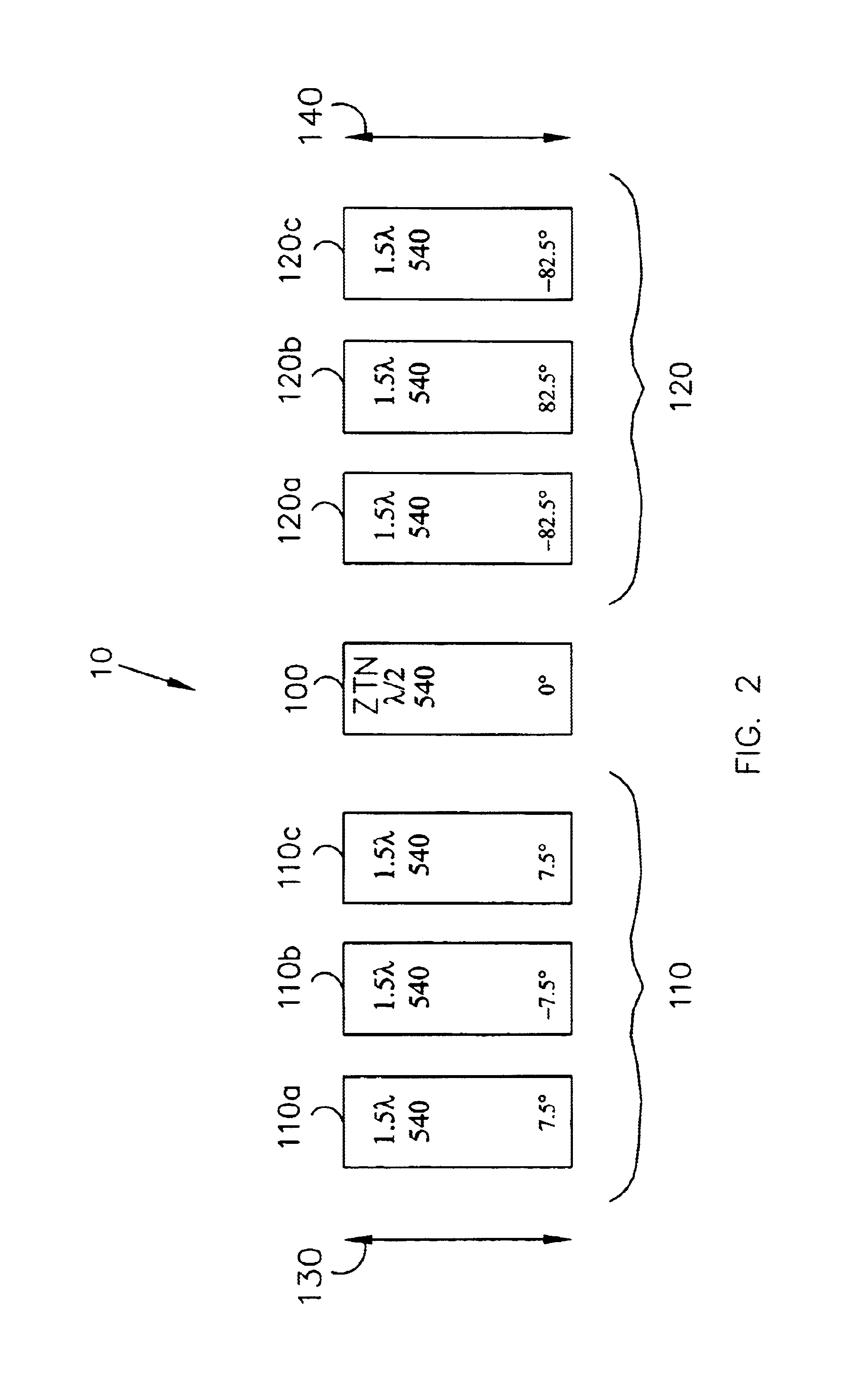
[0130]FIG. 3 magenta / white M / W color filter similar to the color filter shown in FIG. 2, except that the color filter of FIG. 3 transmits a white output in the SA mode. Like the color filter shown in FIG. 2, the ZTN LC modulator 100 is oriented parallel or perpendicular (π / 2) to the input polarizer 130, so that the modulator 100 will modulate 45° polarized light and pass light that is oriented along the polarization axis of the input, polarizer 130 unchanged.

[0131]The first retarder stack 110 comprises individual retarder films 210a, 210b and 210c oriented at 7.5°, −7.5°, and 7.5°, respectively, with respect to the input polarizer 130. The second retarder stack 120 comprises individual retarder films 220a, 220b and 220c oriented at 82.5°, −82.5° and 82.5°, respectively, with respect to the input polarizer 130. The individual retarder films in the first and second retarder stacks 110 and 120 are 1.5-wave retarders in the grain (14...

embodiment 3

tack, π / 4-Oriented ZTN LC Modulator, Crossed Polarizer

[0134]FIG. 4 shows another embodiment of a color filter with a magenta / white output. Like the embodiments shown in FIGS. 2 and 3, the input and exit polarizers 130 and 140 are oriented parallel with respect to each other. However, the ZTN LC half-wave modulator 100 is oriented at the ±π / 4 with respect to the input polarizer 130. Thus, the modulator 100 modulates the polarization of light that is oriented parallel to the polarization axis of the input polarizer 130, and leaves the polarization of light that is oriented at ±π / 4 with respect to the input polarizer 130 unchanged.

[0135]In order to obtain a M / W output like the color filter shown in FIGS. 2 and 3, the first and second retarder stacks 110 and 120 are modified so that they each provide full-wave retardence in the green (140 nanometers). As in the color filter shown in FIG. 2, the first and second retarder stacks 110 and 120 are crossed with respect to each other, thus pro...

embodiment 4

tack, π / 4-Oriented ZTN LC Modulator, Crossed Polarizer

[0137]FIG. 5 shows another embodiment of a CSLM 10 similar to the CSLM shown in FIG. 4, except that a white output is achieved in the SA mode. The ZTN LC half-wave modulator 100 reflects the state of polarization, such that the input polarization appears to be oriented at π / 2, and the first retarder stack 110“appears” to have orientations π / 2−α1, π / 2−α2, . . . π / 2−αN. A SA white state is generated by creating the “appearance” of crossed retarder stacks and parallel polarizers. This is done by orienting the exit polarizer 140 at π / 2, and orienting the individual retarders second retarder stack 120 at −αN, . . . −α1. The resulting structure has first and second retarder stacks 110 and 120 of opposite sign.

[0138]The embodiment shown in FIG. 5, the first retarder stack 110 comprises individual retarders 410a, 410b and 410c, oriented at 22.5°, 75° and −60°, respectively, with respect to the input polarizer 130. The second retarder sta...


PUM


Abstract

The present invention provides a high brightness color selective light modulator (CSLM) formed by a polarization modulator positioned between two retarder stacks. The modulator changes the apparent orientation of one retarder stack relative to the other so that, in a first switching state of the modulator the two retarder stacks cooperate in filtering the spectrum of input light, and in a second switching state the two retarder stacks complement each other, yielding a neutral transmission spectrum. Two or more CSLM stages can be used in series, each stage providing independent control of a primary color. One preferred embodiment eliminates internal polarizers between CSLM stages, thereby providing an additive common-path full-color display with only two neutral polarizers. Hybrid filters can be made using the CSLMs of this invention, in combination with other active or passive filters. The CSLMs of this invention can be used in many applications, particularly in the areas of recording and displaying color images. They can be arranged in a multi pixel array by pixelating the active elements, and can be implemented as color filter arrays, using patterned passive retarders rather than active polarization modulators.

Description

[0001]This application is a Continuation-In-Part application of Ser. No. 08 / 645,580, filed May 14, 1996 now U.S. Pat. No. 5,822,021, the contents of which are incorporated herein by reference in their entirety.BACKGROUND OF THE INVENTION[0002]1. Field of the Invention[0003]This invention relates generally to color selective polarization modulation and, more specifically, to color sequencers for colorizing imaging devices, such as displays and cameras.[0004]2. Background of the Related Art[0005]Full color display is generally implemented using one of four techniques: (1) spatially using color filter arrays; (2) temporally using sequential color techniques; (3) additive superposition using multiple optical paths; or (4) subtractively using stacked display panels. In spatial color systems, each full-color pixel is subdivided into at least three sub-pixels, one dedicated to each additive primary color. A color filter array (CFA), consisting of red, green and blue spectral filters, is re...

Claims


Application Information

Patent Timeline
IPC IPC(8): G02B27/28G02F1/01G02F1/03G02F1/09G02F1/1335G02F1/13363G02F1/1347G02F1/23H04N5/66H04N5/74H04N9/31
CPCG02B27/288H04N9/3197G02F1/13363G02F1/13473G02F1/23H04N5/66H04N9/3111H04N9/3167G02F1/0136G02F1/0322G02F1/09G02F1/133533G02F1/133536G02F2001/133543G02F2001/133638G02F2413/04G02F2413/08H04N5/7441G02F1/133543G02F1/133638
Inventor SHARP, GARY D.
Owner REAID INC
Why Eureka
Try Eureka