Toilet and method of operation

a technology of toilets and toilets, applied in the field of toilets, can solve the problems of increasing the amount of vacuum used, and increasing the possibility of system plugging, so as to improve the quality of flushing

Inactive Publication Date: 2005-04-26
DOMETIC CORP
View PDF8 Cites 18 Cited by
  • Summary
  • Abstract
  • Description
  • Claims
  • Application Information

AI Technical Summary

Benefits of technology

[0010]With the present invention, the operator initiates the flush cycle but does not control the duration. The flush cycle is controlled by the logic implemented by the microprocessor. The water valve is independently controlled from the flush valve. Water starts to flow into the bowl before the flush valve is opened, and the flush valve is opened for an optimum time period. As a consequence, the quality of the flush is improved.
[0011]A second flush before full vacuum is restored is prevented. Additionally, the microprocessor may monitor the vacuum level and prevents the second flush even if the flush lever is activated.

Problems solved by technology

In the vacuum toilet, if the flush valve is open for too short a period of time, insufficient water may accompany the waste, which may increase the possibility of the system plugging.
A short duration flush also limits the amount of vacuum utilized in the flush and reduces the force that macerates the waste, which also increases the possibility of the system plugging.
If the flush valve is open for an extended period of time, then excessive water is utilized.
Additionally, if a second flush cycle is activated before the full level of vacuum is restored, the reduced level of vacuum may not have sufficient force to macerate the sewage, and system plugging may result.
If the flush valve is open for an extended period of time, then excessive water is utilized and it increases the possibility that malodor from the holding tank may enter the bathroom via the flush valve.

Method used


Image

  • Toilet and method of operation
  • Toilet and method of operation
  • Toilet and method of operation

Examples


Embodiment Construction

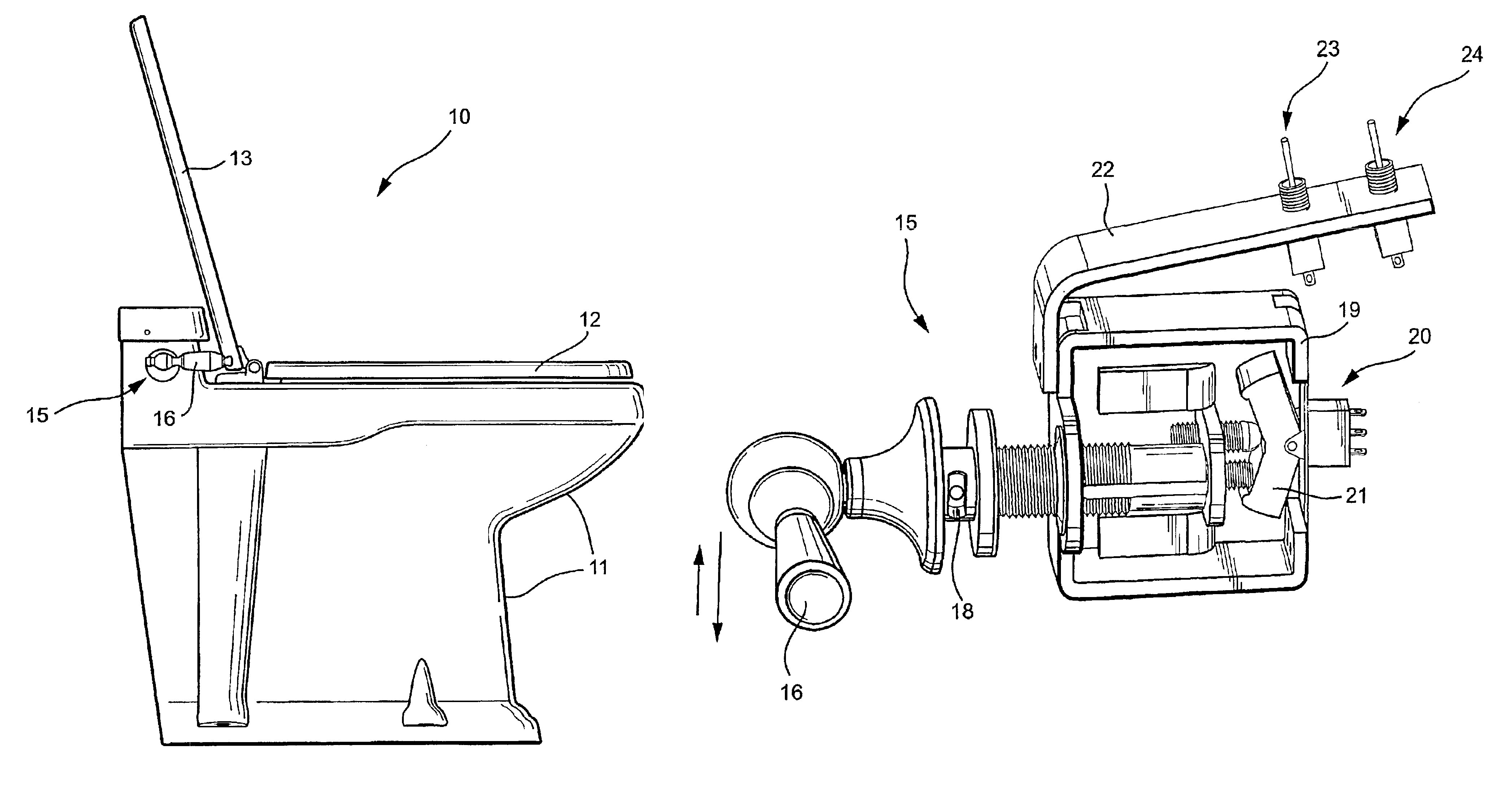
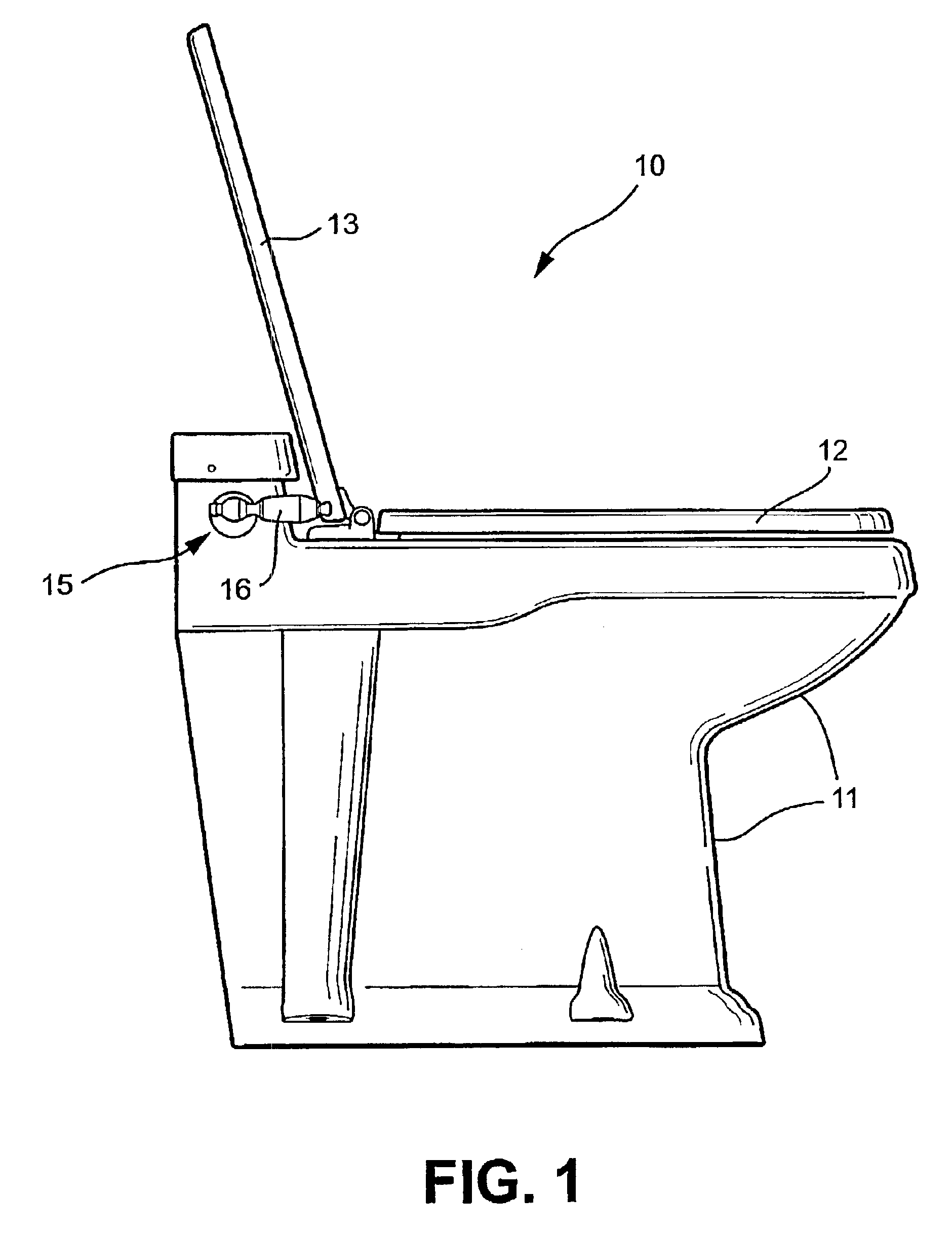
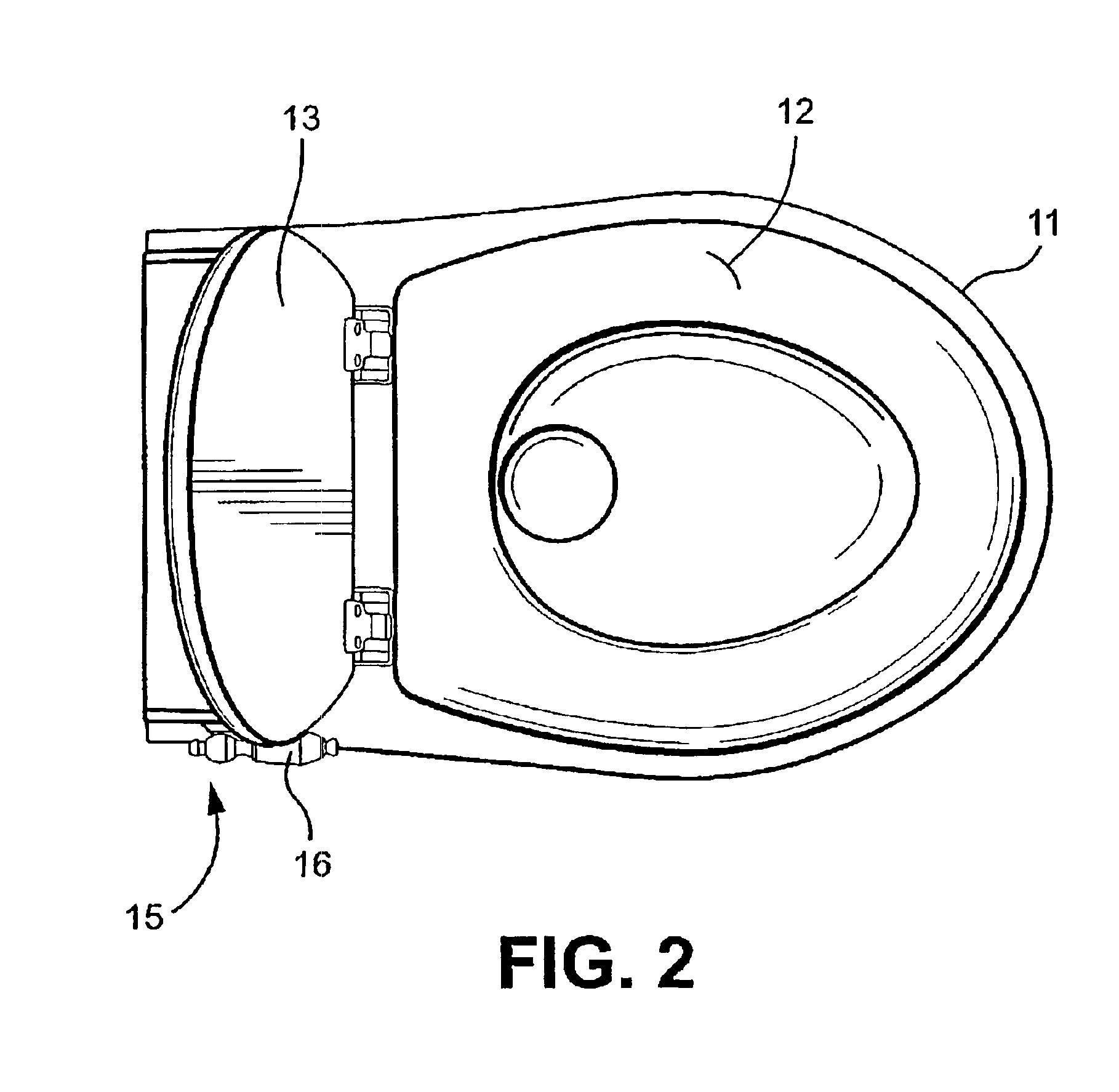
[0027]FIGS. 1-3 show an exemplary toilet 10 (either vacuum or drop through) according to the invention having a substantially all china one-piece combination bowl and base 11, with a conventional toilet seat 12 and cover 13 associated therewith. In exterior appearance, the toilet 10 generally resembles conventional toilets found in homes, businesses and the like. The toilet 10 includes a flush lever assembly 15 associated therewith incorporating an actuating lever 16. An exemplary form of the flush lever assembly 15 is shown in more detail in FIG. 4.

[0028]The flush lever assembly 15 includes a shaft that may be rotated in either clockwise (flush) or counterclockwise (add water) directions about an axis (e.g., a substantially horizontal axis) by manipulating the actuating lever 16 to activate components mounted in the housing 19. In an exemplary embodiment, an electrical switch is mounted at one end of the housing 19 and is actuated to close “add water” contacts or “flush” contacts d...


PUM


Abstract

A toilet (10) and toilet system suitable for a boat, recreational vehicle, bus or the like is operated via a microprocessor controller to effect a convenient and efficient operation. The toilet includes a base assembly (30) having an electrically-operated flush valve that opens and closes a passage to a waste receiving area. A flush lever assembly (15) has flush lever displaceable from a neutral position toward one of a “flush” position and an “add water” position. In this context, the flush lever initiates a flush cycle in the “flush” position and initiates an add water cycle in the “add water” position. The controller communicates with a water inlet valve, the flush valve and the flush lever assembly. In operation, the controller opens and closes the water inlet valve and controls a position of the flush valve in accordance with a position of the flush lever.

Description

[0001]This application claims the benefit of Provisional Application No. 60 / 253,113 filed Nov. 28, 2000.BACKGROUND OF THE INVENTION[0002]The present invention relates to toilets and, more particularly, to a toilet and toilet system that is particularly suitable for a boat, recreational vehicle (RV), bus or the like.[0003]The toilet according to the present invention may either be of the vacuum type (such as generally shown in U.S. Pat. No. 5,621,924, the disclosure of which is hereby incorporated by reference), or the drop through type.[0004]There currently exist in the marine and RV industries, vacuum toilets and gravity drop toilets that are foot pedal or lever operated. These are manually operated toilets where a flush valve is opened by the operator and remains open as long as the operator activates the pedal or lever. In the vacuum toilet, if the flush valve is open for too short a period of time, insufficient water may accompany the waste, which may increase the possibility of...

Claims


Application Information

Patent Timeline
Patent Type & Authority Patents(United States)
IPC IPC(8): B61D35/00B63B29/14B63B29/00E03D3/00E03D5/00E03D5/10E03D1/32E03D3/12E03D5/012
CPCB61D35/005B63B29/14E03D5/10E03D3/00E03D5/012E03D1/32
Inventor SIGLER, JAMES A.SNYDER, NATHAN A.KRIEDER, ROBERT D.MIKO, STEVEN L.THOMAS, RANDALL
Owner DOMETIC CORP
Why Eureka
Try Eureka