
Process for machining axial blade slots in turbine disks for jet engines

a technology of turbine disks and blade slots, which is applied in the direction of machines/engines, manufacturing tools, forging/pressing/hammering apparatus, etc., can solve the problems of large single-purpose machines, long tooling lead-time, and cost-effective cutter tools

Inactive Publication Date: 2005-04-26
RAYTHEON TECH CORP
View PDF13 Cites 48 Cited by
  • Summary
  • Abstract
  • Description
  • Claims
  • Application Information

AI Technical Summary

Benefits of technology

[0005]Accordingly, it is an object of the present invention to provide an improved process for machining axial blade slots in turbine disks used in jet engines.

Problems solved by technology

Broaching presents a number of issues, including costly cutter tools, very long tooling lead-time, very long tooling set-ups, and a very large single-purpose machine requiring a special concrete base and other infrastructure to support it.
's method is not applicable to the creation of internal slots.

Method used


Image

  • Process for machining axial blade slots in turbine disks for jet engines
  • Process for machining axial blade slots in turbine disks for jet engines
  • Process for machining axial blade slots in turbine disks for jet engines

Examples


Embodiment Construction

)

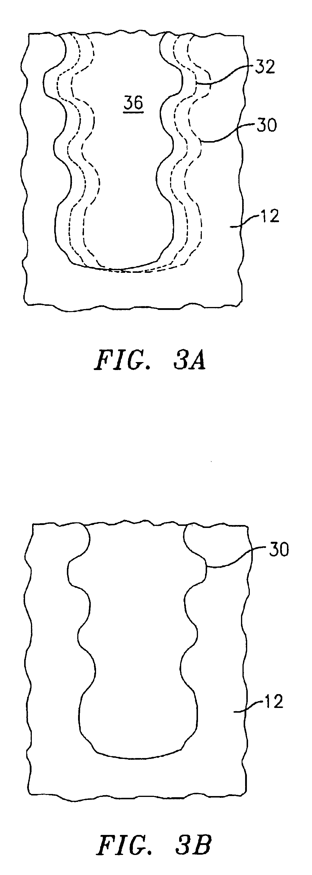
[0014]The present invention relates to a process for machining axial blade slots, such as those designated by the reference numeral 10 in FIG. 1, in turbine disks 12 for use in jet engines. The process initially involves the step of providing a blank turbine disk 12. The blank turbine disk12 may be formed from a nickel based superalloy, a titanium based superalloy, steel, or another suitable material.

[0015]The next step in the process is to form a series of roughened slots 14 in the blank disk 12. Each of the roughened slots 14 has a plurality of joined rectangular areas such as 2, 3, or 4 joined rectangular areas. FIG. 2B illustrates a roughened slot having three rectangular areas 16, 18, and 20. The rectangular areas 16, 18 and 20 may be formed using a grinding machine 22 such as that shown in FIG. 2A and a series of superabrasive grinding wheels 24 connected to a spindle 26. A superabrasive grinding wheel is a class of wheels where the abrasive material is diamond or cubic boron...


PUM

PropertyMeasurementUnit
diameteraaaaaaaaaa
diameteraaaaaaaaaa
diameteraaaaaaaaaa

Abstract

A process for machining axial blade slots in turbine disks used in jet engines is provided. The process broadly includes the steps of providing a turbine disk, forming a roughened slot having a plurality of joined rectangular areas in the turbine disk, and machining the roughened slot to a finished slot.

Description

BACKGROUND OF THE INVENTION[0001]The present invention relates to a process for machining axial blade slots in turbine disks for jet engines.[0002]Retention slots are a design feature of turbine disks. The slots are used to hold or retain turbine blades around the periphery of the disk. Current practice in the aerospace industry is to machine these slots into the disk by use of a broaching machine, which is a linear cutting machine that drives successively larger cutters through the disk slot, with the final cutters having the fir tree or other appropriate shape of the finished slot. One technique which employs broaching is illustrated in U.S. Pat. No. 5,430,936 to Yadzik, Jr. et al. Broaching presents a number of issues, including costly cutter tools, very long tooling lead-time, very long tooling set-ups, and a very large single-purpose machine requiring a special concrete base and other infrastructure to support it.[0003]Another method for producing profiled parts is illustrated ...

Claims


Application Information

Patent Timeline
Patent Type & Authority Patents(United States)
IPC IPC(8): B24B1/00B24B19/02B24B19/00B24B19/14B23P13/00B23P13/02B23P15/00B23C3/00B23C3/34F01D5/00F01D5/30B23C3/30B21D28/28F01D5/02F01D5/28F02C7/00
CPCB23C3/30B23P13/02B23P15/006B24B1/00B24B19/02F01D5/3007B24B19/14B23C2220/366Y10T29/49996F05D2230/10Y10T29/49321Y10T29/47Y10T29/4932B21D28/28
Inventor PACKMAN, ALLAN B.VAILLETTE, BERNARD D.
Owner RAYTHEON TECH CORP
Features
  • Generate Ideas
  • Intellectual Property
  • Life Sciences
  • Materials
  • Tech Scout
  • Unparalleled Data Quality
  • Higher Quality Content
  • 60% Fewer Hallucinations
Learn More