Aircraft engine with inter-turbine engine frame

a technology of engine frame and engine body, which is applied in the direction of machines/engines, efficient propulsion technologies, mechanical apparatuses, etc., can solve the problems of increasing engine weight, length, cost, and weight of supporting frames, and reducing engine clearance performance, so as to improve clearance performance and reduce cost and weight. , the effect of improving the clearance performan

Inactive Publication Date: 2005-04-26
GENERAL ELECTRIC CO
View PDF20 Cites 307 Cited by
  • Summary
  • Abstract
  • Description
  • Claims
  • Application Information

AI Technical Summary

Benefits of technology

[0012]The present invention replaces a turbine rear frame with an outer guide vane assembly that results in cost and weight reduction benefits by using the turbine transition duct spacing to incorporate an inter-turbine frame to rotatably support both HP and LP rotors. Improved clearance performance results from LP shaft critical speed being disengaged from the HP rotor spee

Problems solved by technology

Bearing supporting frames are heavy and add weight, length, and cost to the engine.
The frames, especially those located in the engine hot section, are complex and expensive.
Counter-rotatin

Method used


Image

  • Aircraft engine with inter-turbine engine frame
  • Aircraft engine with inter-turbine engine frame
  • Aircraft engine with inter-turbine engine frame

Examples


Embodiment Construction

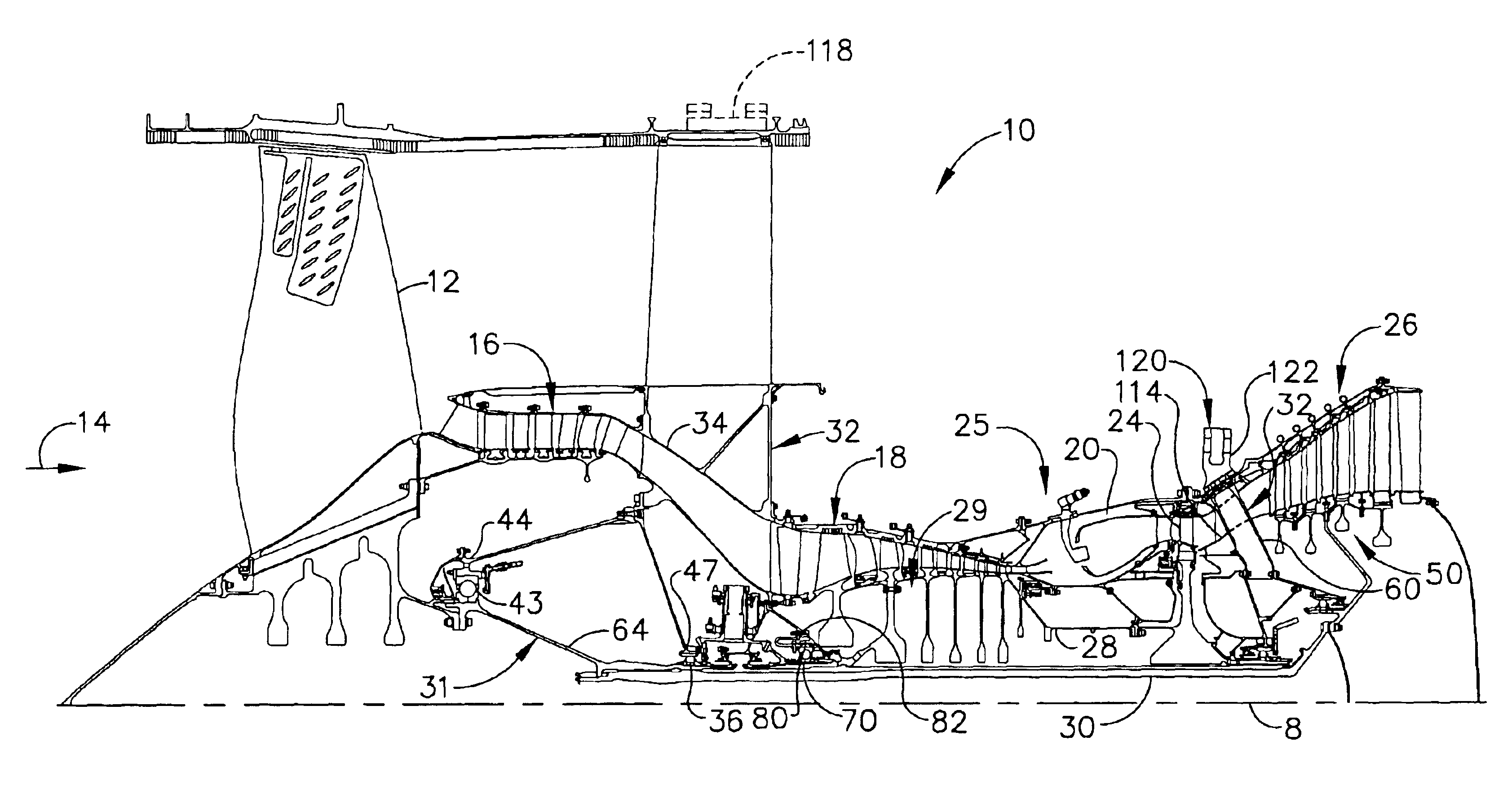
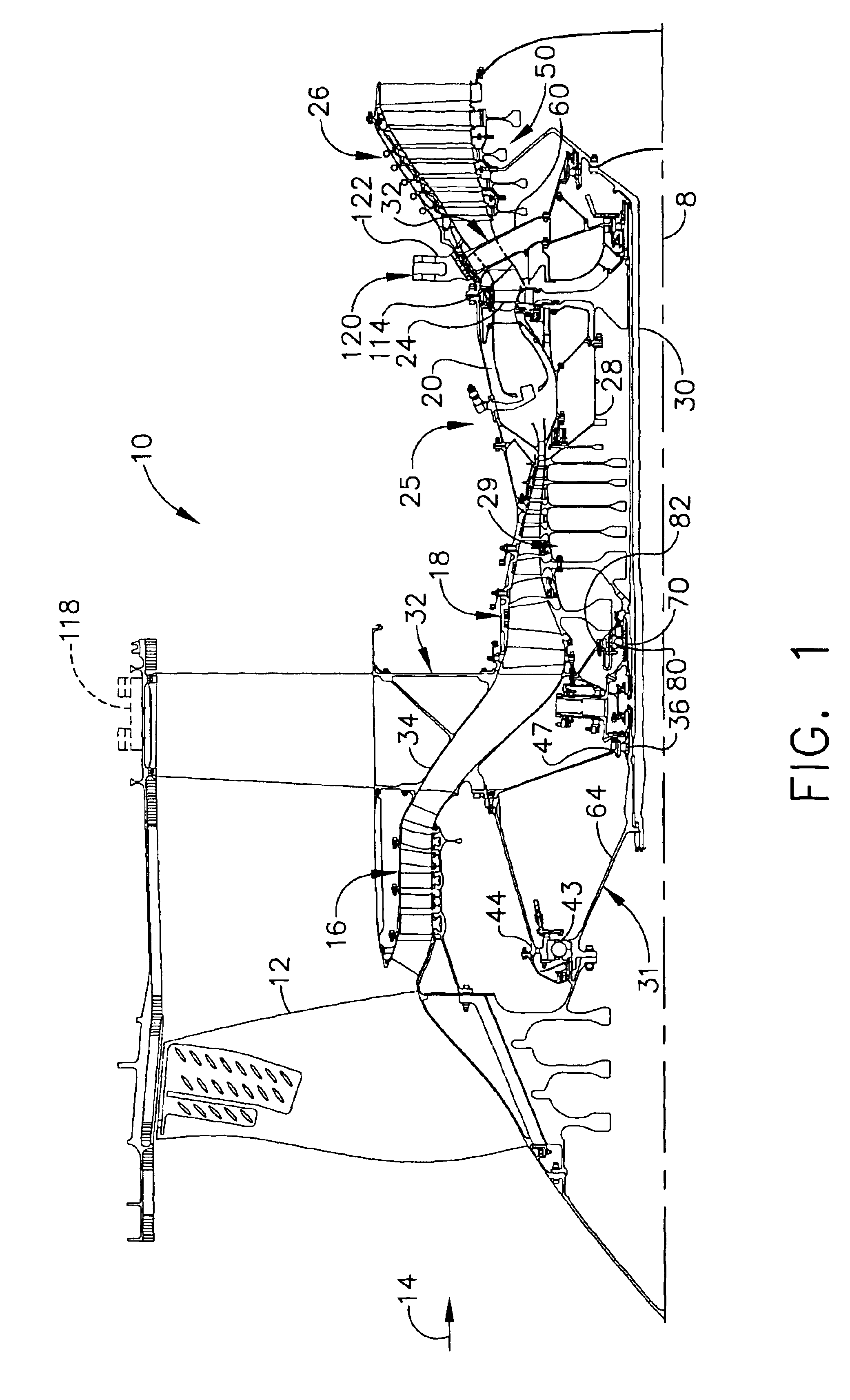
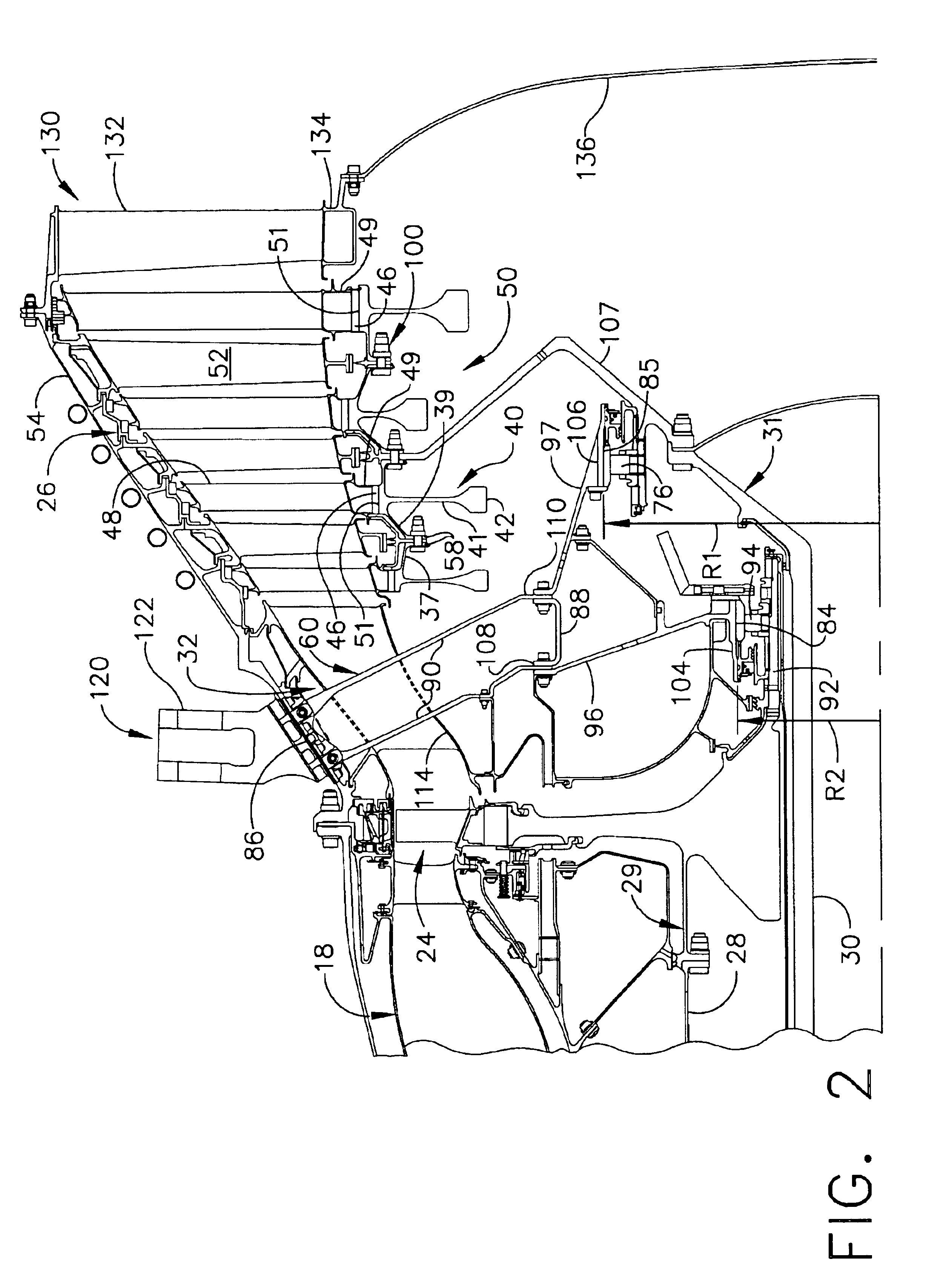
[0018]Illustrated schematically in FIGS. 1 and 2 is a first exemplary turbofan gas turbine engine 10 circumscribed about an engine centerline axis 8 and having a fan 12 which receives ambient air 14, a booster or low pressure compressor (LPC) 16, a high pressure compressor (HPC) 18, a combustor 20 which mixes fuel with the air 14 pressurized by the HPC 18 for generating combustion gases which flow downstream through a high pressure turbine (HPT) 24, and a low pressure turbine (LPT) 26 from which the combustion gases are discharged from the engine 10. A first or high pressure shaft 28 joins the HPT 24 to the HPC 18 to substantially form a first or high pressure rotor 29. A second or low pressure shaft 30 joins the LPT 26 to both the fan 12 and the low pressure compressor 16 to substantially form a second or a low pressure rotor 31. The high pressure compressor (HPC) 18, combustor 20, and high pressure turbine (HPT) 24 collectively are referred to as a core engine 25 which includes, f...


PUM


Abstract

An aircraft engine turbine frame includes a first structural ring, a second structural ring disposed co-axially with and radially spaced inwardly of the first structural ring about a centerline axis. A plurality of circumferentially spaced apart struts extend between the first and second structural rings. Forward and aft sump members having forward and aft central bores are fixedly joined to forward and aft portions of the turbine frame respectively. A frame connecting means for connecting the engine to an aircraft is disposed on the first structural ring. The frame connecting means may include a U-shaped clevis. The frame may be an inter-turbine frame axially located between first and second turbines of first and second rotors of a gas turbine engine assembly. An axial center of gravity of the second turbine passes though or very near a second turbine frame bearing supported by the aft sump member.

Description

CROSS REFERENCE TO RELATED APPLICATION(S)[0001]This is a divisional of application Ser. No. 09 / 997,461 filed on Nov. 29, 2001, now U.S. Pat. No. 6,708,482, which is hereby incorporated by reference herein.BACKGROUND OF THE INVENTION[0002]1. Field of the Invention[0003]The invention relates to aircraft gas turbine engines and, particularly, for such engines having frames that support the rotors in bearings and are used to mount the engines to the aircraft.[0004]2. Description of Related Art[0005]A gas turbine engine of the turbofan type generally includes a forward fan and booster compressor, a middle core engine, and an aft low pressure power turbine. The core engine includes a high pressure compressor, a combustor and a high pressure turbine in a serial flow relationship. The high pressure compressor and high pressure turbine of the core engine are interconnected by a high pressure shaft. The high pressure compressor, turbine, and shaft essentially form the high pressure rotor. The...

Claims


Application Information

Patent Timeline
IPC IPC(8): F01D25/16F01D25/28F01D5/06F02K3/06
CPCF01D25/162F01D25/28Y02T50/671Y02T50/60
Inventor SEDA, JORGE F.
Owner GENERAL ELECTRIC CO
Why Eureka
Try Eureka