Front end structure

Inactive Publication Date: 2005-04-26
DENSO CORP
View PDF68 Cites 40 Cited by
  • Summary
  • Abstract
  • Description
  • Claims
  • Application Information

AI Technical Summary

Benefits of technology

[0006]In view of the points described above, the object of the present invention is to p

Problems solved by technology

However, since parts are required in order to make up a duct structure portion, it is difficult to reduce the number of parts and assembly steps.
Also, in the case where the additional parts are assembled with a lower accuracy, sufficient hermetic sealing cannot be ensured between the condenser and the radiator, wi

Method used


Image

  • Front end structure
  • Front end structure
  • Front end structure

Examples


first embodiment

(First Embodiment)

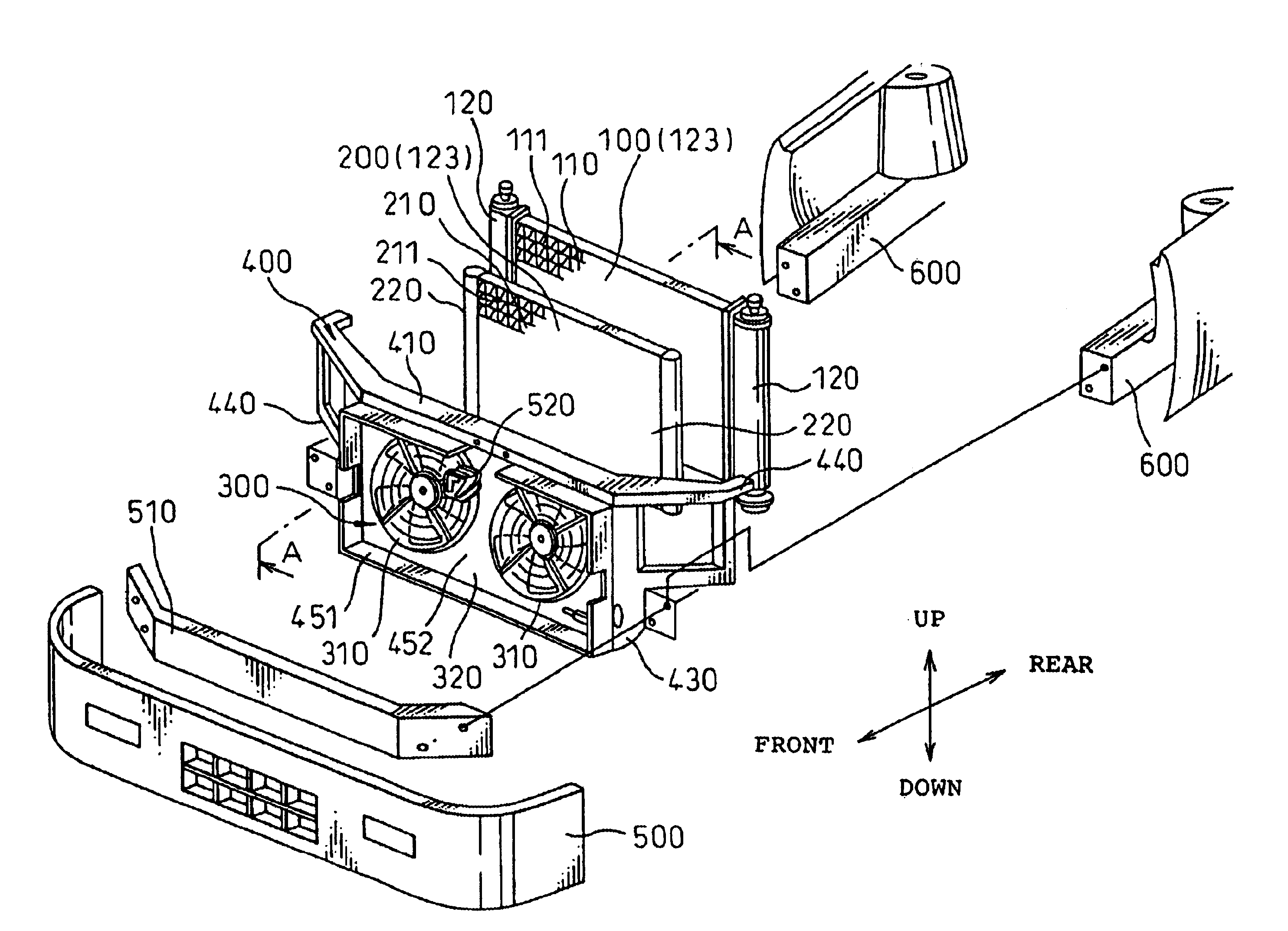
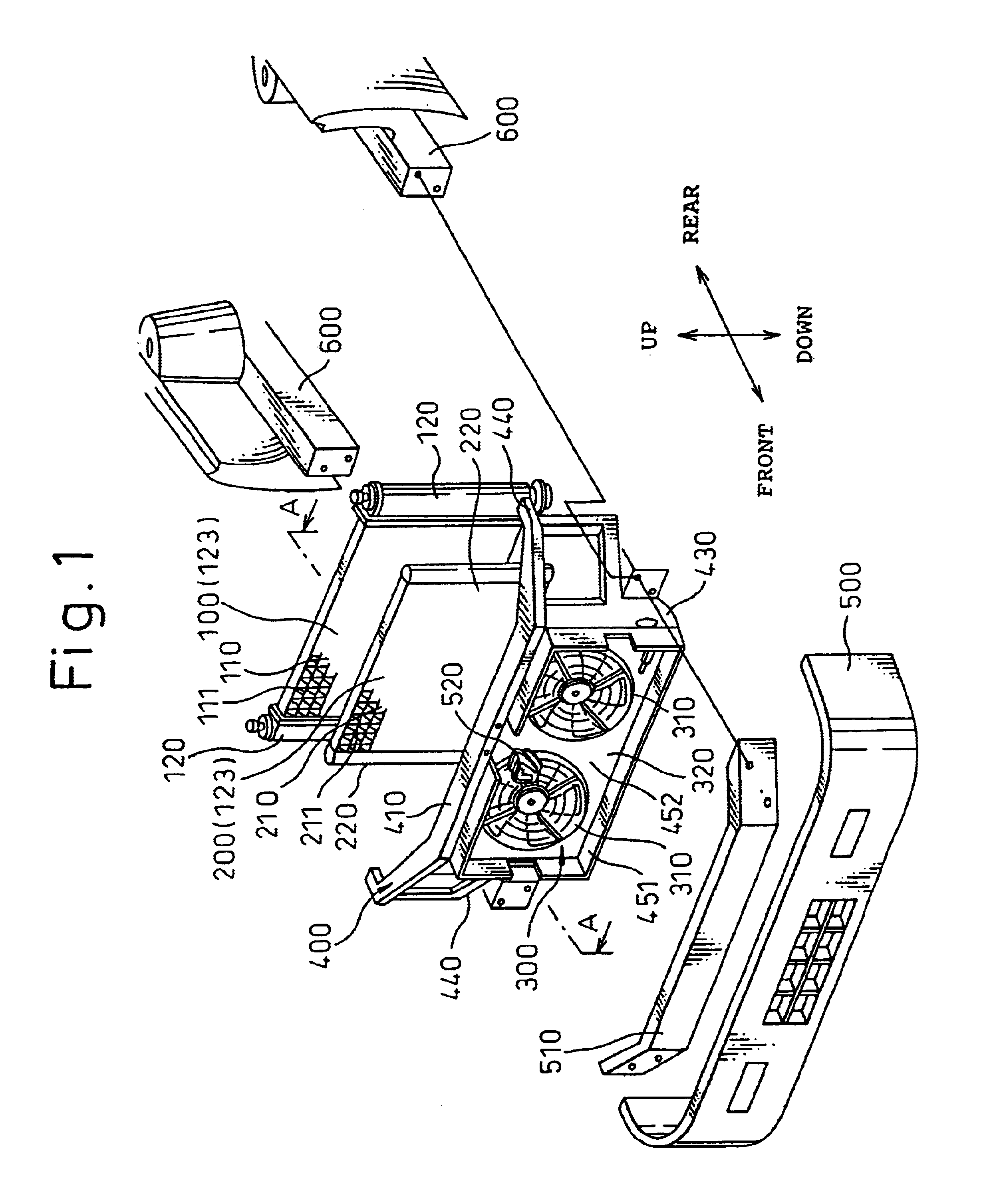
[0019]This embodiment represents a case in which a radiator for cooling the cooling water for an engine (internal combustion engine) to drive the vehicle, a condenser for condensing by cooling the refrigerant circulating in the refrigeration cycle (air conditioning system) of the vehicle and a fan unit for blowing the cooling air to the radiator and the condenser make up the vehicle front end parts mounted on the vehicle front end portion. FIG. 1 is an exploded perspective view of a front end structure according to this embodiment.

[0020]In FIG. 1, numeral 100 designates a radiator, numeral 200 a condenser and numeral 300 a fan unit. The fan unit 300, the condenser 200 and the radiator 100 are mounted on the vehicle in that order in series from the upstream side (the vehicle front end side) along the air flow.

[0021]The fan unit 300 includes axial flow fans 310 and a shroud 320 having stays 325 for holding the axial flow fans 310 while at the same time hermetically s...

second embodiment

(Second Embodiment)

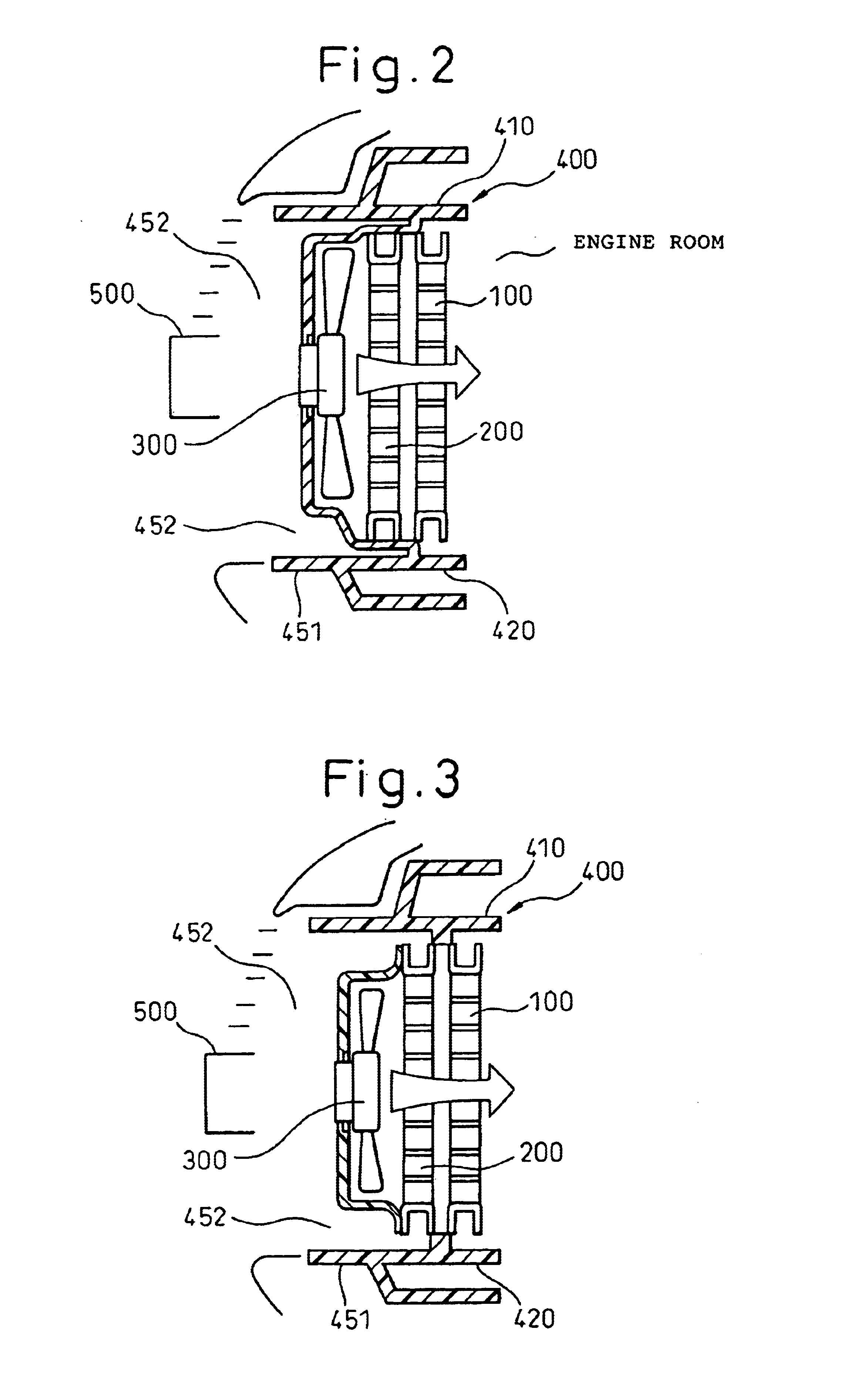
[0043]According to this embodiment, unlike in the first embodiment having the panel 400 and the shroud 320 integrated with each other, the panel 400 and the shroud 320 are formed as members independent of each other and the fan unit 300 is fixedly assembled on the condenser 200 and the radiator 100 by fastening means such as a bolt, as shown in FIG. 3.

[0044]This facilitates maintenance work (repair and / or exchange) conducted on the fan unit 300 at a dealer or a service station.

third embodiment

(Third Embodiment)

[0045]According to the first and second embodiments, the condenser 200 and the radiator 100 are fixedly assembled on the panel 400 independently. In the present embodiment, on the other hand, as shown in FIG. 4, the condenser 200 and the radiator 100 are assembled on the panel 400 after being integrated with each other.

[0046]According to this embodiment, the condenser 200 and the radiator 100 are integrated with each other by side plates (brackets) 110 each making up a reinforcing member of the condenser 200 and the radiator 100. At the same time, the side plates (brackets) 110 constitute a duct structure for preventing the air introduced from the grille opening 452 from bypassing the condenser 200 and the radiator 100.

[0047]Each of the side plates 110 is arranged on an end portion of the condenser 200 and the radiator 100, both substantially rectangular, and extends in parallel to the tubes to reinforce the heat exchange core formed of the tubes and the fins.

[0048...


PUM


Abstract

A front end structure includes a front end panel (400) that is configured as a duct structure for preventing the air introduced from a grille opening (452) from bypassing a condenser (200) and a radiator (100). A fan unit (300) is arranged on the most upstream side portion of the structure. As a result, without the need to provide parts making up a separate duct structure, fresh air flow temperature can be blown in, while at the same time, the air that has passed through the condenser (200) can be prevented from bypassing the radiator (100). Thus, the heat releasing capacity of the condenser (200) and the radiator (100) can be improved while simultaneously preventing leakage between the condenser (200) and the radiator (100) without adding complex structure.

Description

CROSS-REFERENCE TO RELATED APPLICATIONS[0001]This application is based upon and claims priority from Japanese Patent Application No. 2000-027271, filed Jan. 31, 2000, No. 2000-303584, filed Oct. 3, 2000 and No. 2000-365237, filed Nov. 30, 2000, and is a continuation of PCT / JP01 / 00681, filed Jan. 31, 2001.TECHNICAL FIELD[0002]The present invention relates to a structure at the front end portion (front end) of an automotive vehicle on which heat exchangers such as a radiator and a condenser are mounted.BACKGROUND ART[0003]In a method of mounting (fixing) a condenser at the front end portion of an automotive vehicle according to the invention described in Japanese Unexamined Patent Publication No. 5-71891, a condenser supporting portion is used to constitute a duct structure portion for hermetically closing the gap between the condenser and the radiator so that the flow of the air that has passed through the condenser is prevented from bypassing the radiator.[0004]However, since parts ...

Claims


Application Information

Patent Timeline
IPC IPC(8): B60K11/04B60K11/02B62D29/00B62D29/04B62D25/08
CPCB60K11/04B62D29/04B62D25/084
Inventor OZAWA, IKUOSUGIYAMA, TOSHIKISASANO, NORIHISAMAEDA, NORIAKIKURATA, SHUN
Owner DENSO CORP
Why Eureka
Try Eureka