
Controlled-articulation trailer with synchronized steering and a travelling top link tool bar hitch

a technology of synchronized steering and tool bar hitch, which is applied in the direction of tractor steering, agriculture tools and machines, applications, etc., can solve the problems of small work vehicles that cannot accomplish the things, can not achieve the same degree of speed or quality, and the impact force of small work vehicles is much less, so as to reduce the stress on the hitch. , the effect of large loads

Inactive Publication Date: 2005-04-26
GUNDERSON GENE
View PDF11 Cites 7 Cited by
  • Summary
  • Abstract
  • Description
  • Claims
  • Application Information

AI Technical Summary

Benefits of technology

[0012]It is an object of the present invention to allow relatively small work vehicles to lift, handle and move relatively large implements which potentially themselves bear large loads while reducing the stress on the hitch, the trailer and the draft vehicle.
[0013]Another object of the invention is to provide increased mobility and stability to work vehicle combinations in rough terrain or hillside work.
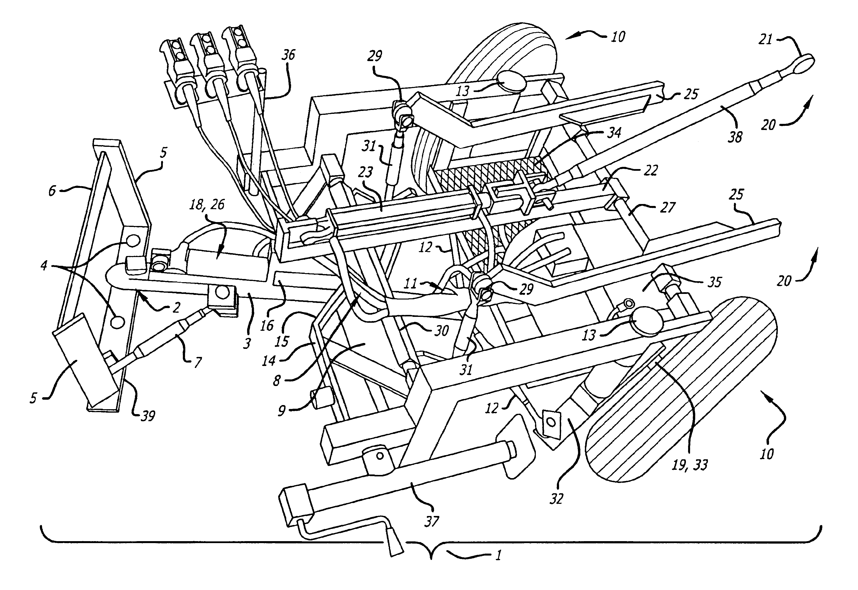
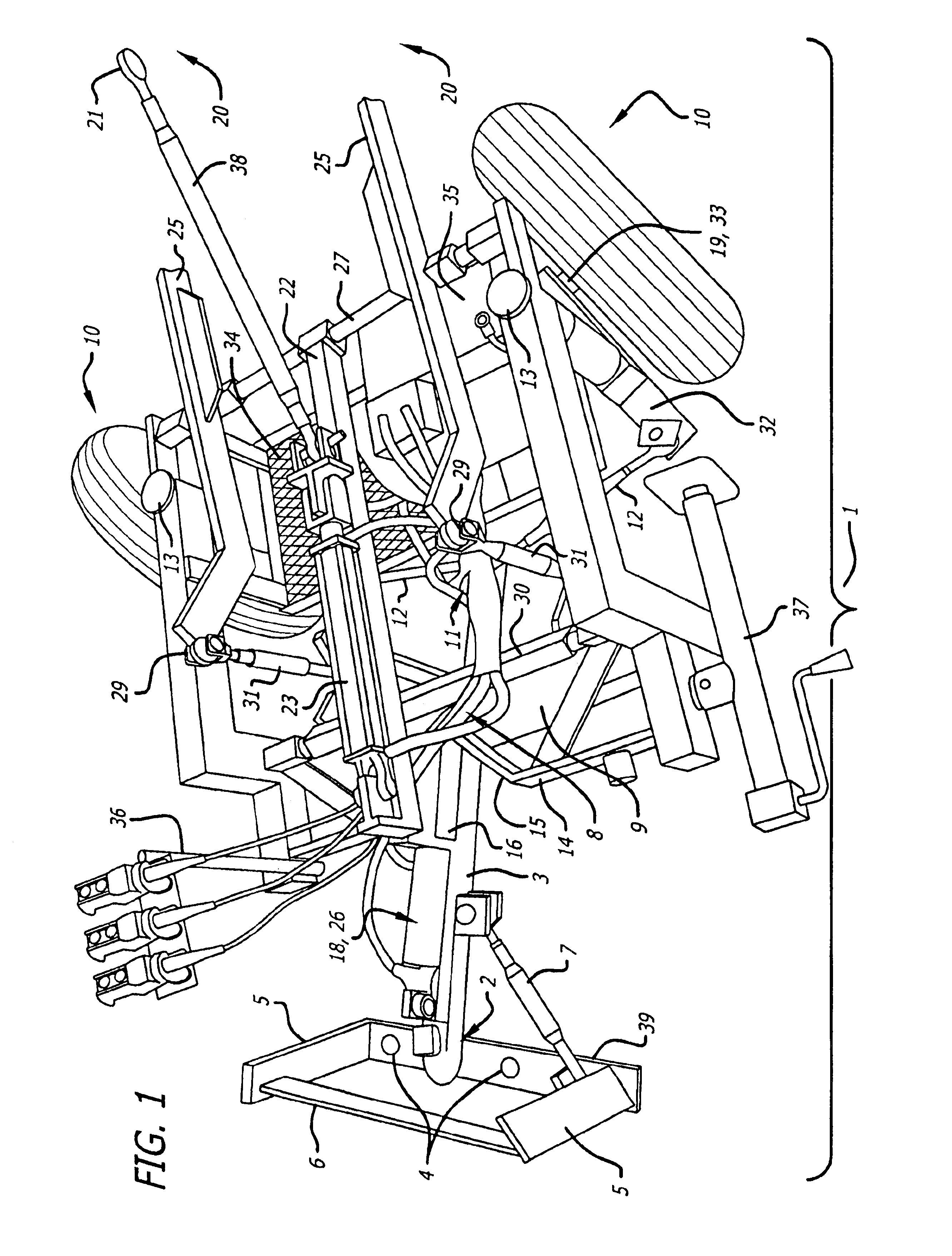
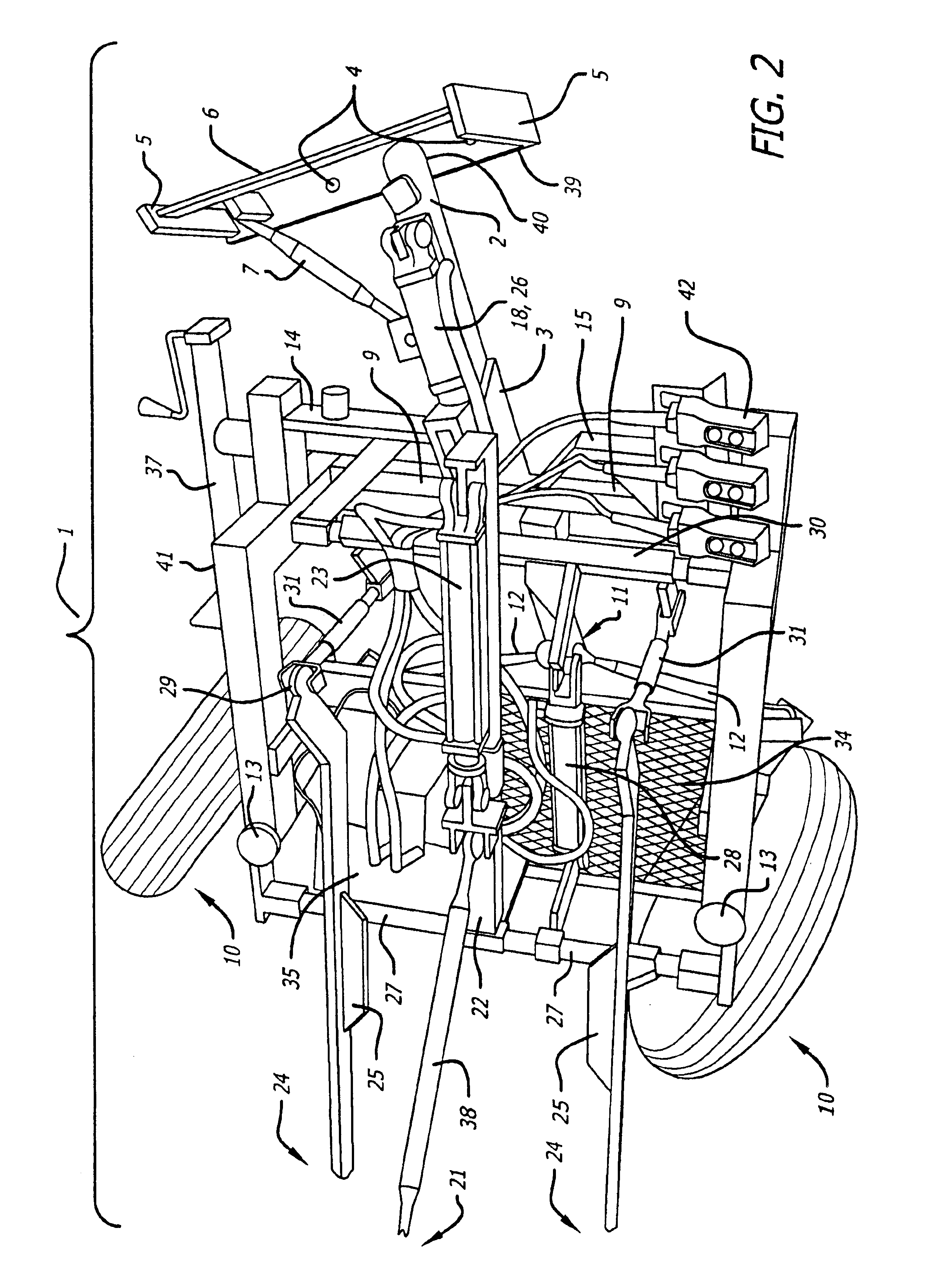
[0015]To synchronize the steering, the invention mechanically utilizes seven pivot points, a tongue pivot across the frame, dual pivots for each of two tie-rods, and the pivot of each of the two wheels respectively. An angular transfer system controls the radial movement of the trailer's back axles during turning. The trailer wheels turn in response to turns made by the draft vehicle thus allowing for a much more stable trailing action and tighter turns on varied terrain and / or with heavier loads. The trailer and implement load remains in a linear straight line configuration with the draft vehicle. This eliminates dangerous jack knifing at the draft vehicle draw bar.
[0016]The articulation may be further controlled by a hydraulic ram-bolt, riding along the tongue in and out of a V-mount rigidly attached to the frame, located near the middle-front of the carriage. This system allows the operator to ‘override’ the mechanical synchronization to any desired degree, thereby further controlling the articulation of the vehicle combination. The system may be used to ‘lock’ in and allow any or no degree of synchronization by the trailer. This same system may also be used to center or steer the trailer when backing up.
[0017]The invention utilizes a traveling top link for use with a three point tool bar hitch adapted for use with a work vehicle. The fulcrum of the three point hitch can be moved forward or backward relative to the weight bearing wheels by so moving the top link which travels along a frame-mounted rail hydraulically or otherwise; thereby greatly increasing the potential weight of the implement / load. Although standard three point hitch movements can still be made (the three links moving together or the two bottom links moving while the top link stays stationary), moving the top link only allows the operator of the present invention to consistently return the implements to desired previous positions.
[0019]The synchronized steering design together with the controlled-articulation and the general size, allow for increased stability when trailing a work vehicle and especially when handling heavy loads. The traveling nature of the three point hitch's' top-link allows the trailer to lift and carry heavier loads than those possible under current trailer or attachment designs for use with ATVs, small scale tractors, or animal-drawn carts.

Problems solved by technology

Generally however, these smaller work vehicles cannot accomplish the things that a large-scale farm tractor can, at least not with the same degree of speed or quality.
There are drawbacks with either of these methods which generally force smaller work vehicles to hitch to and manipulate smaller, and typically much less useful and / or efficient, implements.
Such an attached hitch (i) increases the length of the work vehicle thereby decreasing mobility and sight-lines and (ii) imposes a directly opposing force on the work vehicle thereby limiting the scale and weight which can be carried in the hitched implement.
Additionally, front-mounted direct hitches move the implement laterally as the work vehicle is being turned—an undesirable effect especially when the hitched implement is engaged in the ground.
Generally however, as the trailer becomes smaller and lighter, the weight of the hitched implement and corresponding load typically reduces at an even faster rate for a number of reasons.
Either way, the fulcrum of the load remains fixed back of the trailer's axle, thereby limiting the allowable weight of the implement.
Additionally, the movement of a typical three point hitch limits the consistency of position with which the operator can return the attached implement.
Moreover, typical three point hitch trailers, like any standard-steering trailer, have a tendency to jackknife (i.e. the point of attachment between the trailer and the draft vehicle becomes an uncontrolled articulation) and are exceedingly unstable, especially on varied terrain—a tendency which grows (along with the severity-of-result) with the weight of the hitched implement and corresponding load.
The uncontrolled articulation of the typical vehicle combination can present problems.
As anyone who has tried can attest, backing up a trailing vehicle or vehicle combination is very hard.
There is an increased tendency to jackknife and it is difficult to maneuver the vehicle combination to the desired location.
Because of the reasons briefly described above, small-scale work vehicles cannot easily handle the larger round bales—and they certainly cannot do so in varied or wooded terrain.

Method used


Image

  • Controlled-articulation trailer with synchronized steering and a travelling top link tool bar hitch
  • Controlled-articulation trailer with synchronized steering and a travelling top link tool bar hitch
  • Controlled-articulation trailer with synchronized steering and a travelling top link tool bar hitch

Examples


Embodiment Construction

[0032]Various embodiments of the present invention are shown and described. It is to be understood that though these embodiments are shown and described in isolation, various features of each embodiment can be combined with the others to produce a variety of embodiments.

[0033]The present invention is directed to a separate-axle wheeled box-frame trailer 1 equipped with a traveling top-link three point hitch, an attachable dumping flatbed (not shown) and synchronized steering with the degree of articulation controlled. At the fore of the trailer 1 is a hitch-plate 39 with ball, goose neck or other attachment 2 which is received by a female coupling 40 welded to the tongue 3 of the trailer 1. The hitch plate 39 has holes 4 to match the hole spacing on the draw bar of the draft vehicle. Welded to the plate 39 are risers 5 and a horizontal rail 6 to accommodate saddle weights if additional weight on the tongue 3 is necessary. This hitch plate 39 is bolted securely to the draw bar of the...


PUM


Abstract

A controlled articulation trailer with synchronized steering and a traveling top link three point tool bar hitch is disclosed. The controlled articulation trailer comprises a box-frame carriage having two separate but laterally aligned, wheeled axles near the back of the carriage. The aligned axles are mechanically angularly controlled by, or ‘synchronized to’, the movements of the draft vehicle. A tongue attaches to the draft vehicle via a hitch plate bolted to the draw bar of the draft vehicle. The tongue receiver fits onto a ball hitch and an adjustable stabilizer arm is bolted to the hitch plate and extends at an angle back to a tongue attachment. The tongue connects through the front of the carriage to a pivot point located on a bridge across the front-middle of the carriage and extends beyond this pivot point to connect, through doubly-pivoting tie-rods, to the wheels, thus controlling the articulation such that the trailer's wheels turn in synchronization to turns made by the draft vehicle. A hydraulic ram-bolt and V-mount system is located near the front of the carriage such that the ram-bolt, riding along the tongue, may be moved in and out of the V-mount thereby allowing the manual override of the synchronization which further controls the degree of articulation and to some extent allows the operator to further control the position of the trailer relative to the draft vehicle. A weight-bearing front axle may be pivotally mounted near the front of the carriage to help reduce tongue weight on the tongue. A three point tool bar hitch system is mounted near the back of the carriage above the back wheels, the top link of which may be hydraulically or otherwise moved along a rail which is rigidly-mounted to the frame so to enable the operator to ‘pull’ or ‘push’ the fulcrum of the lifting three point hitch as desired.

Description

REFERENCE TO RELATED APPLICATIONS[0001]This application claims the benefit of priority of U.S. Provisional Application No. 60 / 322,517, filed Sep. 12, 2001.FIELD OF THE INVENTION[0002]The present invention relates to an agricultural implement-carrying trailer with a mounted three point tool bar hitch assembly and more particularly to an articulating trailer with synchronized steering and a traveling top link hitch, capable of lifting an implement from, or holding an implement in, a field-use position.BACKGROUND OF THE INVENTION[0003]The use of small-scale work vehicles—vehicles such as animal-drawn forecarts, all terrain vehicles (“ATVs”) and small-scale tractors—is greatly increasing. Generally however, these smaller work vehicles cannot accomplish the things that a large-scale farm tractor can, at least not with the same degree of speed or quality. Because of economics and otherwise, there is a desire for a tool which would allow these smaller work vehicles to do much of what large...

Claims


Application Information

Patent Timeline
Patent Type & Authority Patents(United States)
IPC IPC(8): B62D13/04B62D13/00B62D13/02
CPCB62D13/04B62D13/025
Inventor GUNDERSON, GENE
Owner GUNDERSON GENE
Learn More