Machine tool

a technology of machine tools and troughs, which is applied in the field of machine tools, can solve the problems of obstructing the collection of chips and machining fluids in the trough, reducing the area of the opening of the trough, and increasing production costs, so as to achieve the effect of allowing feeding tolerance and simple configuration

Inactive Publication Date: 2005-04-26
MAKINO MILLING MASCH CO LTD
View PDF13 Cites 21 Cited by
  • Summary
  • Abstract
  • Description
  • Claims
  • Application Information

AI Technical Summary

Benefits of technology

[0008]The invention is directed to solve the problems of the prior art, and the object of the invention is to provide a machine tool which ensures the collection and ejection of the chips with a simple configuration.
[0011]As described above, the single feed screw is provided outside of the trough and adjacent one of the guides. This provide a simple table feeding mechanism and larger trough opening so that the chips and the machining fluid can easily fall into the trough. A single cover disposed outside of the trough can cover both the one of the guides and the single feed screw. This cover cooperates with another cover for covering the other guides to introduce the chips and the machining fluid into the trough. By appropriately adjusting the distance between the guides and the table, allowable feeding tolerance is ensured if the feed screw is offset relative to the center of the table. Therefore, this configuration is more simple compared with the configuration of the two screws with a symmetric rotation of prior art.
[0012]Further, the single common machining fluid pump supplies the machining fluid to the process nozzle and the chip conveyer nozzle. When the workpiece is processed, the machining fluid is distributed to the nozzles to remove the chips from the machining zone and to wash the chips into the trough as mach as possible with a minimum flow of the machining fluid for preventing the collection of the chips on the workpiece, the workpiece mount, the top of the table, the cover and the others. When the process is terminated, the machining fluid is supplied only to the chip conveyer nozzle. This allows all amount of the machining fluid discharged from the pump to be discharged through the chip conveyer nozzle to ensure the eject of the chips, which has fallen in the trough, out of the machine.

Problems solved by technology

Therefore, the area of the opening of the trough is reduced by the cover, which obstructs the collection of the chips and the machining fluid in the trough.
Therefore, there are problems that the configuration becomes complex and the production cost is increased.
The provision of the mechanical chip conveyer in the trough results in the problems of the complex configuration and increase in the production cost.

Method used


Image

  • Machine tool
  • Machine tool
  • Machine tool

Examples


Embodiment Construction

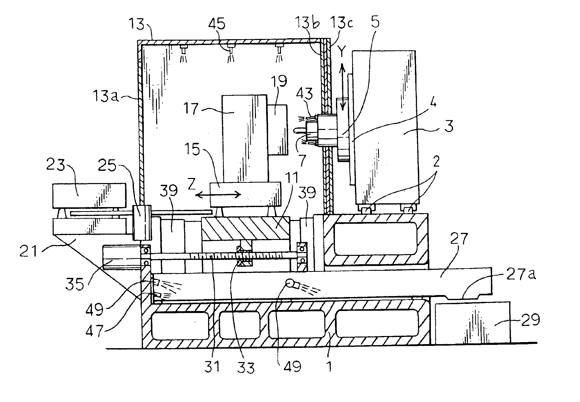
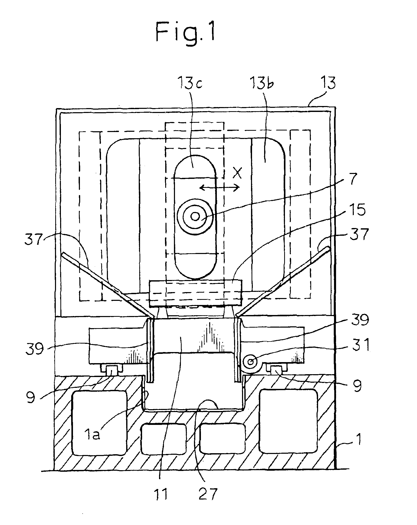
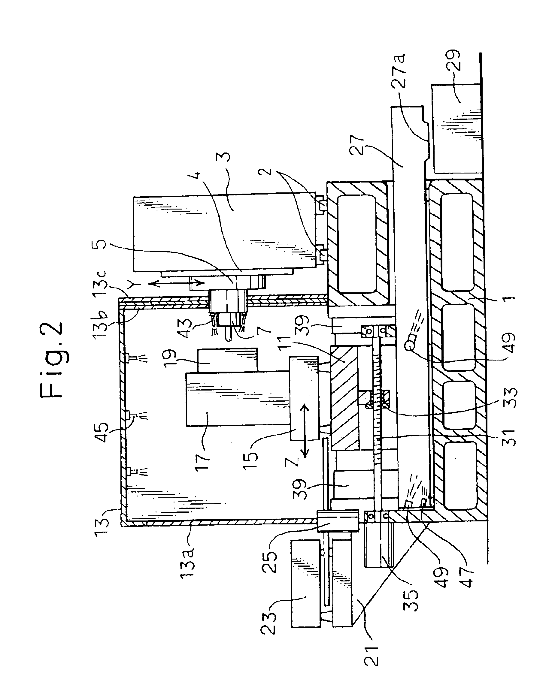
[0017]A machine tool is composed of a bed 1, a column 3 movable in X-axis along a pair of guides 2 extending in left-and-right direction along ridges provided in the rear part of the bed 1, a spindle head 5 movable in Y-axis along a pair of guides 4 extending in up-and-down direction along the front face of the column 3, a spindle 7 rotationally provided in the spindle head 5 and receiving a tool at the end thereof, a table 11 movable in Z-axis along a pair of guides 9 extending back-and-forth direction along the top face of the front part of the bed 1 and a splashguard 13 which encloses the machining zone to prevent the chips and the machining fluid from spreading out.

[0018]A pallet 15 is detachably mounted on the table 11. A workpiece 19 is secured to the pallet 15 through a workpiece mount 17. The workpiece 19 is processed through the relative movement in X-, Y- and Z-axes between the tool on the rotating spindle 7 and the workpiece 17. A pallet base 21 is mounted to the front en...


PUM

PropertyMeasurementUnit
sizeaaaaaaaaaa
pressureaaaaaaaaaa
areaaaaaaaaaaa

Abstract

The invention relates to a machine tool which processes a workpiece through the relative motions between a tool and the workpiece in X-, Y- and Z-axes three directions. The object of the invention is to ensure the collection and ejection of the chips with a simple configuration. The invention comprises a trough 27 provided in the central part of a bed 1 to extend in back-and-forth direction, a pair of guides 9 disposed at left-and-right sides of the trough 27, a Z-axis feed screw 31 disposed adjacent one of the guides 9, and slant covers 37 and Z-axis telescopic covers 39 for covering the pair of guides 9 and the Z-axis feed screw 31. Chip conveyer nozzles 47 and 49 are provided within the trough 27 for directing the machining fluid to eject the chips from the machine.

Description

FIELD OF THE INVENTION[0001]The invention relates to a machine tool such as a milling machine and machining center for processing a workpiece through relative movements between the workpiece and a tool in X-, Y- and Z-axes, and in particular to a machine tool including a splashguard enclosing the machining zone and a trough, disposed under a bed, for receiving the chips and machining fluid to eject them out of the machine.BACKGROUND ART[0002]In the field of machine tools, effective ejection of the chips and machining fluid has been one of the important subjects for the research and development. For example, Japanese Unexamined Patent Publication (Kokai) No. 10-328968 describes a machine tool as a first prior art. This comprises a splashguard for enclosing a machining zone, a trough extending in the back-and-forth direction along the center of a bed, guides, provided on the bed at the left-and-right sides of the trough, for the back-and-forth motion of a table, the table being dispos...

Claims


Application Information

Patent Timeline
Patent Type & Authority Patents(United States)
IPC IPC(8): B23Q11/00B23Q11/08B23Q7/14B23Q11/10
CPCB23Q11/0891B23Q11/10B23Q7/1431B23Q11/0057Y10T409/304088Y10T409/30392Y10T409/304032Y02P70/10
Inventor MAEDA, MASAHIRO
Owner MAKINO MILLING MASCH CO LTD
Why Eureka
Try Eureka