Methods and apparatus for securing multi-piece nozzle assemblies

a multi-piece, nozzle technology, applied in the direction of forging/pressing/hammering apparatus, machines/engines, liquid fuel engines, etc., can solve the problems of complex cooling scheme to reduce operating temperature within the airfoil, and the nozzle trailing edge being the life-limiting location of the nozzl

Inactive Publication Date: 2005-04-26
GENERAL ELECTRIC CO
View PDF7 Cites 59 Cited by
  • Summary
  • Abstract
  • Description
  • Claims
  • Application Information

AI Technical Summary

Benefits of technology

[0006]In another aspect of the invention, a nozzle assembly for a turbine engine is provided. The nozzle assembly includes a plurality of nozzles that each include an outer band, an inner band and an airfoil. The airfoil has a suction side and a pressure side connected at a leading edge and a trailing edge, such that a cooling cavity is defined within the airfoil. The leading and trailing edges of the airfoil extend between the inner and the outer band. A member extends through said cooling cavity of said airfoil, and at least one of said inner band and said outer band. The member is secured within the nozzle assembly with at least one fastener such that the member is coupled adjacent to at least one of th...

Problems solved by technology

The combination of such stresses and temperatures may result in the vane trailing edge being the life limiting location of the nozzle.
The overall efficiency of the gas turbine engine is directly related to the temperature of the combustion gases, a...

Method used


Image

  • Methods and apparatus for securing multi-piece nozzle assemblies
  • Methods and apparatus for securing multi-piece nozzle assemblies
  • Methods and apparatus for securing multi-piece nozzle assemblies

Examples


Embodiment Construction

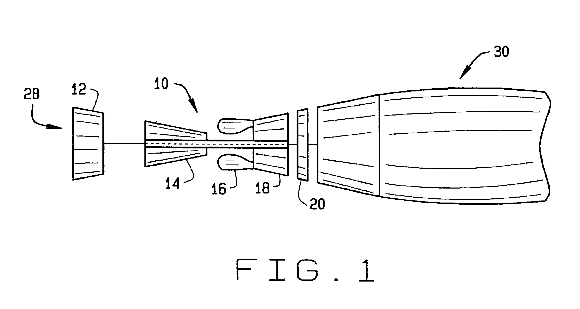
[0013]FIG. 1 is a schematic illustration of a gas turbine engine 10 including a low-pressure compressor 12, a high-pressure compressor 14, and a combustor 16. Engine 10 also includes a high-pressure turbine 18 and a low-pressure turbine 20. Engine 10 has an intake, or upstream, side 28 and an exhaust, or downstream, side 30. In one embodiment, engine 10 is a turbine engine commercially available from General Electric Power Systems, Schenechtady, N.Y.

[0014]In operation, air flows through low-pressure compressor 12 and compressed air is supplied to high-pressure compressor 14. The highly compressed air is delivered to combustor 16. Airflow from combustor 16 is discharged through a turbine nozzle assembly (not shown in FIG. 1) that includes a plurality of nozzles (not shown in FIG. 1) and used to drive turbines 18 and 20. Turbine 20, in turn, drives low-pressure compressor 12, and turbine 18 drives high-pressure compressor 14.

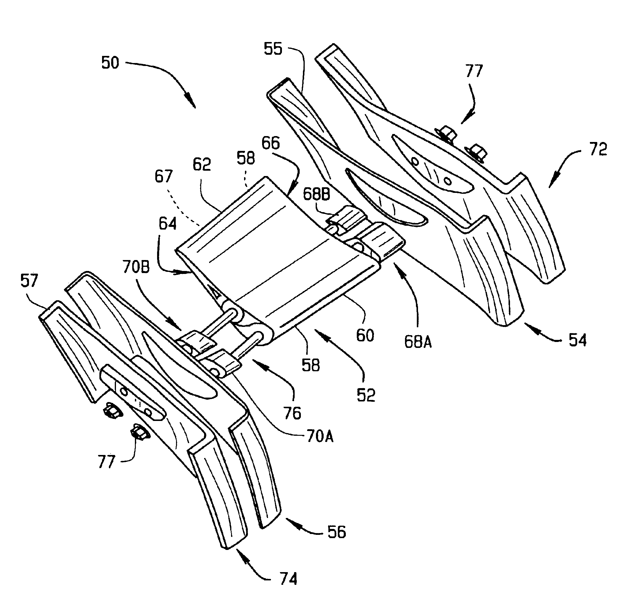
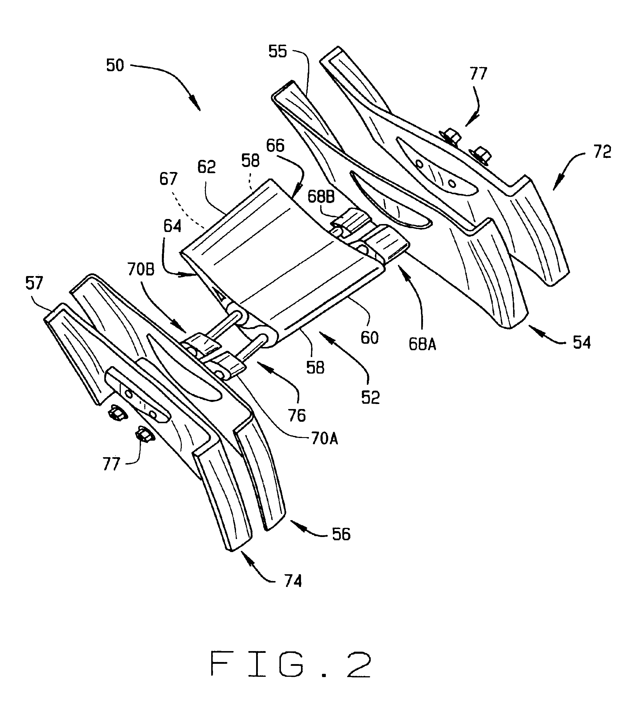
[0015]FIG. 2 is an exploded view of a turbine nozzle 50 that...


PUM

PropertyMeasurementUnit
Pressureaaaaaaaaaa
Tensionaaaaaaaaaa

Abstract

A method for securing a nozzle for a turbine is provided. The nozzle includes an airfoil having a suction side and a pressure side connected at a leading edge and a trailing edge such that a cooling cavity is defined within the airfoil, the airfoil extending between an inner band and an outer band. The method includes extending at least one member through the airfoil, and at least one of the inner band and the outer band. The method further includes securing the nozzle assembly in position with at least one fastener such that the at least one member is coupled adjacent to at least one of the inner band and the outer band.

Description

BACKGROUND OF THE INVENTION[0001]This invention relates generally to turbine engine nozzles and more particularly, to methods and apparatus for securing multi-piece nozzle assemblies.[0002]At least some known turbine engines include a turbine nozzle assembly which channels flow towards a turbine. At least some known turbine nozzle assemblies include a plurality of nozzles arranged circumferentially within the engine. Each nozzle includes an airfoil vane that extends between inner and outer band platforms. Each airfoil vane includes a pair of sidewalls that are connected at a leading edge and a trailing edge.[0003]During operation, the nozzles are typically cooled by a combination of internal convective cooling and gas side film cooling. Typically, the metal temperature distribution of a vane airfoil is such that the trailing edge is significantly hotter than a temperature of the bulk of the airfoil. The temperature gradient created may induce compressive stresses at the vane trailin...

Claims


Application Information

Patent Timeline
IPC IPC(8): F01D9/04
CPCF01D9/042Y10T29/49323F05D2240/10F05B2260/301
Inventor DARKINS, JR., TOBY GEORGEDUNN, DANIEL GENEGRACE, CHRISTOPHERCORMAN, GREGORY SCOTSCHRODER, MARK STEWART
Owner GENERAL ELECTRIC CO
Why Eureka
Try Eureka