Independently controlled read and write head stripe height parameters in slider back end process

a back end process and independent control technology, applied in the direction of grinding machine components, manufacturing tools, lapping machines, etc., can solve the problems of adding variations of some critical write head dimensions, and the head may be scrapped

Active Publication Date: 2005-04-26
HEADWAY TECH INC
View PDF3 Cites 91 Cited by
  • Summary
  • Abstract
  • Description
  • Claims
  • Application Information

AI Technical Summary

Benefits of technology

[0013]One objective of the present invention is to provide a lapping method for independently controlling critical

Problems solved by technology

Furthermore, any in-process misalignment between the wafer plane and the ABS lapping plane also results in added variations of some critical write h

Method used


Image

  • Independently controlled read and write head stripe height parameters in slider back end process
  • Independently controlled read and write head stripe height parameters in slider back end process
  • Independently controlled read and write head stripe height parameters in slider back end process

Examples


Embodiment Construction

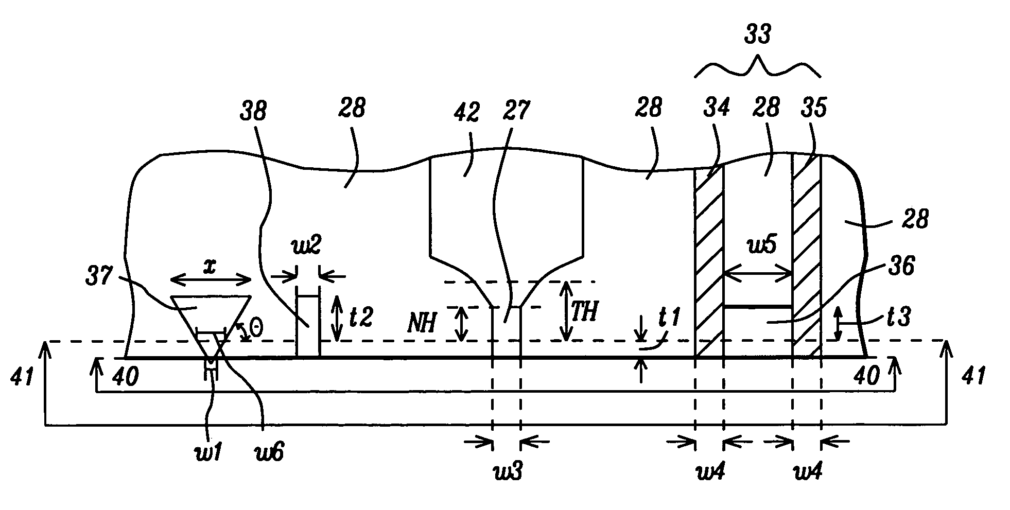
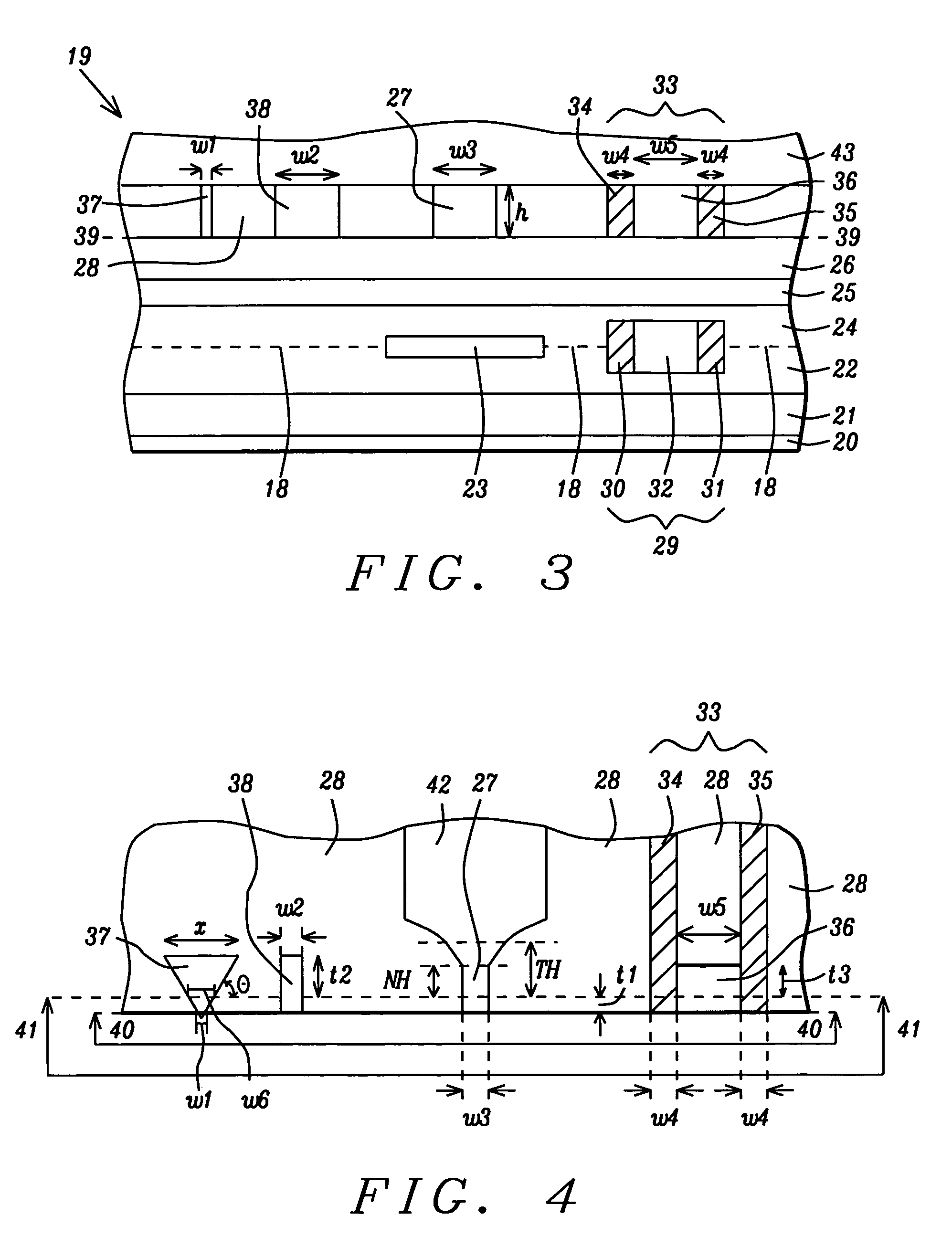
[0028]The present invention involves an improved lapping guide system which enables independent control of the neck region dimensions that are perpendicular to the ABS in a merged read / write head. Although a perpendicular magnetoresistive (PMR) design is shown in the drawings, the present invention is equally applicable to other write head structures including a planar writer or a stitched pole writer. The drawings are provided by way of example and are not intended to limit the scope of the invention. Additionally, the figures are not necessarily drawn to scale and the relative sizes of the various elements may be different than in an actual device. The present invention is also a method for lapping a merged read / write head by employing the lapping guide system disclosed herein.

[0029]First, the lapping guide system of the present invention will be described. Referring to FIG. 3, a first embodiment is shown in a cross-sectional view from a lapping plane of a merged read / write head ...


PUM


Abstract

A lapping guide system and method for lapping a merged read/write head are disclosed. The resistance RRE of a first ELG near the sensor in the read head is correlated to the resistance RWE of a second ELG and to the width of a first optical lapping guide (OLG) near the neck region of the write head. As the lapping progresses, RWE and RRE increase and the OLG width along the lapping plane increases. Thus, an OLG width and a RWE corresponding to a target neck height or throat height and a RRE corresponding to a target stripe height are determined. A lapping plane is actively tilted to enable write head dimensions to be independently controlled on a per wafer or per row basis. The first OLG is a triangular feature with one side parallel to the lapping plane and the other two sides converging near the lapping plane.

Description

FIELD OF THE INVENTION[0001]The invention relates to a method for independently controlling write head dimensions perpendicular to the ABS plane and read head stripe height during a lapping process and is also a system that includes an electrical lapping guide and an optical lapping guide in the plane of the write head for controlling the lapping process.BACKGROUND OF THE INVENTION[0002]When manufacturing magnetic heads for magnetic storage applications, a critical step is a milling (lapping) process in which material from one side of the head is trimmed to form an air bearing surface (ABS). Typically, a plurality of heads is arranged side by side in row that has been sliced from a substrate and mounted on a lapping plate in front of a lapping tool. Once the lapping process is complete, the row is diced to form individual heads. Each head is formed on a slider which in the final device is attached to a servo control unit that guides the head over a spinning recording medium during a...

Claims


Application Information

Patent Timeline
IPC IPC(8): B24B37/04G11B5/31
CPCB24B37/30B24B37/042
Inventor DOVEK, MORISCHEN, WENJIE
Owner HEADWAY TECH INC
Why Eureka
Try Eureka